Wing flutter model frame segment structure

A technology of flutter model and frame segment, which is applied in the field of flutter test device design, can solve the problems of insufficient model aesthetics and time-consuming replacement status, and achieve the effects of saving test time, reducing test cost and improving accuracy

Inactive Publication Date: 2019-06-04
XIAN AIRCRAFT DESIGN INST OF AVIATION IND OF CHINA
0 Cites 2 Cited by

AI-Extracted Technical Summary

Problems solved by technology

[0002] When designing the flutter model of an aircraft wing surface, the beam frame is used to simulate the stiffness of the wing surface, and the wooden frame section is used to simulate the shape of the wing surface. Use mask paper to...

Abstract

The invention discloses a wing flutter model frame segment structure, and belongs to the technical field of flutter test device design. The wing flutter model frame segment structure comprises a metalbeam, a leading edge, a trailing edge, a skin cover plate, common ribs, a reinforcing rib, a self-locking device, a self-locking push rod and clamping pins, wherein the leading edge, the trailing edge and the common ribs at the left and right sides are mutually connected to form a main frame, and the reinforcing rib is arranged in the main frame and used for connecting the leading edge and the trailing edge; the metal beam passes through the common ribs and the reinforcing rib and is connected with the reinforcing rib so as to install the whole main frame on the metal beam; the skin cover plate is provided with skin ribs with the clamping pins and limited on the common ribs at two sides through the clamping pins; one end of the reinforcing rib is provided with the self-locking device, andthe skin cover plate is provided with the self-locking push rod; and the skin cover plate is detachably installed on the main frame through the cooperation of the self-locking push rod and the self-locking device. In the test process, the wing flutter model frame segment structure can effectively save the test time and reduce the test cost, ensures the smooth and neat appearance of the frame segment and improves the accuracy of the test result.

Application Domain

Technology Topic

Image

  • Wing flutter model frame segment structure
  • Wing flutter model frame segment structure
  • Wing flutter model frame segment structure

Examples

  • Experimental program(1)

Example Embodiment

[0038] In order to make the objectives, technical solutions and advantages of the present invention clearer, the technical solutions in the embodiments of the present invention will be described in more detail below with reference to the accompanying drawings in the embodiments of the present invention. Throughout the drawings, the same or similar reference numbers refer to the same or similar elements or elements having the same or similar functions. The described embodiments are some, but not all, of the embodiments of the present invention. The embodiments described below with reference to the accompanying drawings are exemplary, and are intended to explain the present invention and should not be construed as limiting the present invention. Based on the embodiments of the present invention, all other embodiments obtained by those of ordinary skill in the art without creative efforts shall fall within the protection scope of the present invention. The embodiments of the present invention will be described in detail below with reference to the accompanying drawings.
[0039] In the description of the present invention, it should be understood that the terms "center", "portrait", "horizontal", "front", "rear", "left", "right", "vertical", "horizontal", The orientation or positional relationship indicated by "top", "bottom", "inner", "outer", etc. is based on the orientation or positional relationship shown in the drawings, and is only for the convenience of describing the present invention and simplifying the description, rather than indicating or implying that The device or element referred to must have a specific orientation, be constructed and operate in a specific orientation, and therefore should not be construed as limiting the scope of protection of the present invention.
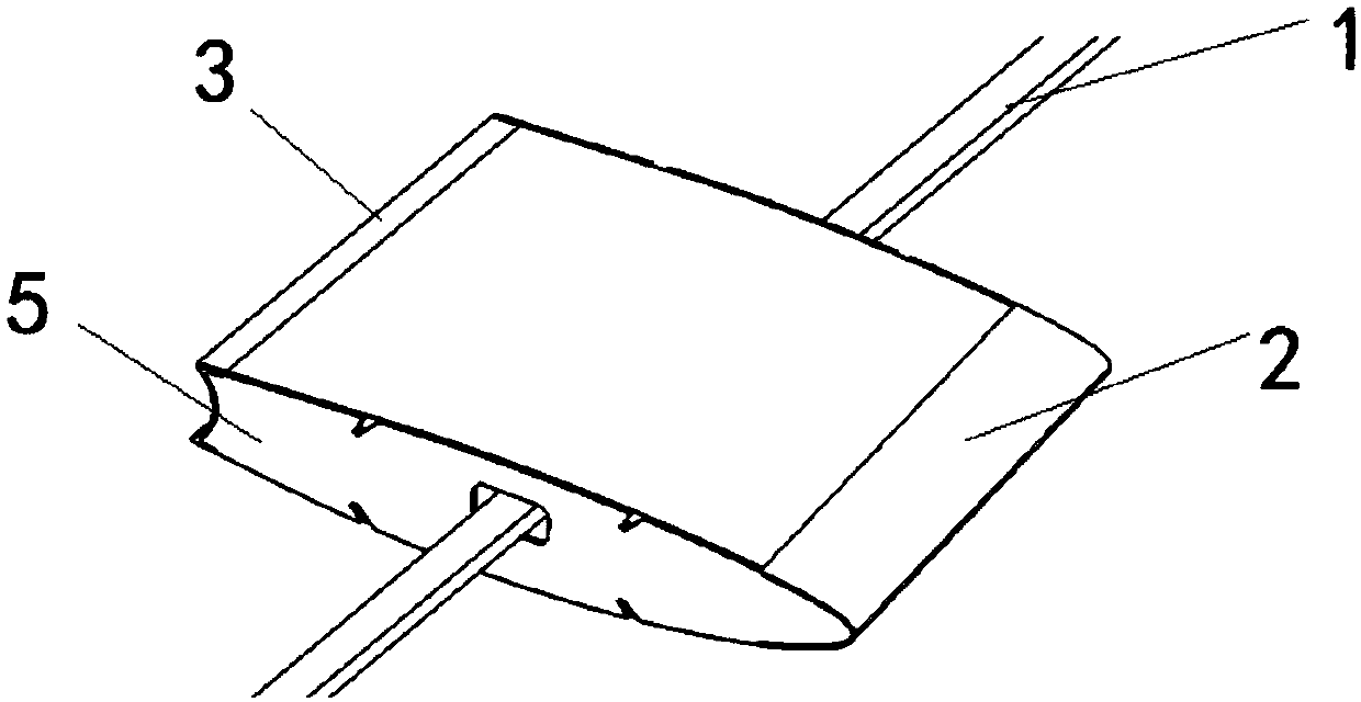
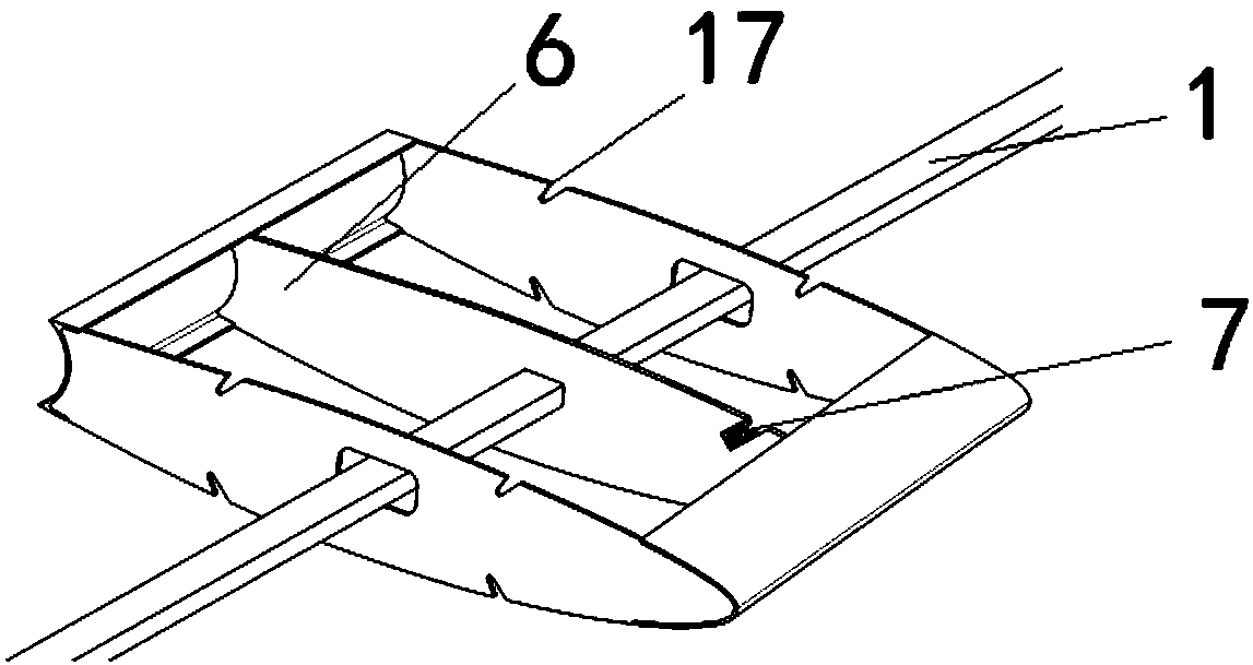
[0040] like Figure 1 to Figure 7 A frame segment structure of an airfoil flutter model, comprising: a metal beam 1, a leading edge 2, a trailing edge 3, a skin cover 4, a common rib 5, a reinforcing rib 6, a self-locking device 7, a self-locking pusher Rod 9 and bayonet 10;
[0041] The front edge 2, the rear edge 3 and the common ribs 5 on the left and right sides are connected to each other to form the main frame, and the reinforcing rib 6 is arranged in the main frame for connecting the front edge 2 and the rear edge 3;
[0042] In this embodiment, the leading edge 2 and the trailing edge 3 are glued on the reinforcing rib 6 through AB, and the two common ribs 5 are glued between the leading edge 2 and the trailing edge 3 through AB glue.
[0043] The common rib 5 is provided with a through hole for the metal beam 1 to pass through, and the reinforcing rib 6 is provided with a mounting hole, and the mounting hole fits the metal beam 1 with clearance;
[0044] The metal beam 1 passes through the common rib 5 and the reinforcing rib 6 and is bonded with the reinforcing rib 6 by AB glue, and the entire main frame is installed on the metal beam 1 .
[0045] In this embodiment, the upper and lower ends of the common rib 5 are symmetrically provided with limiting grooves 17 , the limiting grooves 17 are arranged obliquely along the common rib 5 , the limiting grooves 17 are arranged in cooperation with the bayonet 10 , and the limiting grooves 17 located on the same side open toward Consistent. When installing the common rib 5 , any mounting edge of the common rib 5 can be used to limit the bayonet 10 .
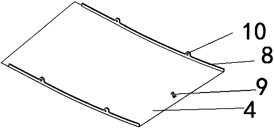
[0046] The skin cover plate 4 is vertically provided with skin ribs 8 along its left and right sides. The skin ribs 8 are glued to the edge position of the skin cover plate through AB, and the skin ribs 8 are uniformly distributed along the horizontal direction. bayonet 10;
[0047] One end of the reinforcing rib 6 is provided with a self-locking device 7, and the skin cover 4 is provided with a self-locking push rod 9 which is installed in cooperation with the self-locking device 7;
[0048] The skin cover plate 4 is limited on the common ribs 5 on both sides by the bayonet 10, and is detachably installed on the main frame through the self-locking push rod 9 in cooperation with the self-locking device 7.
[0049] In this embodiment, the self-locking device 7 includes: a housing 11 , a spring clip 12 , a pressure spring 14 and a limit hook 15 ;
[0050] Among them, the shell is composed of a bottom plate, two side clips and an outer plate;
[0051] A pressure spring 14 is arranged in the casing. The two ends of the pressure spring 14 are respectively connected to the spring clamp plate 12 and the bottom plate of the casing. The spring clamp plate 12 moves up and down along the clamping edge of the casing under force, and one end is provided with a clamping part for locking. Self-locking push rod; the spring clamp plate 12 is provided with a limit hook 15, one end of the limit hook 15 is mounted on the spring clamp plate 12, and the other end is clamped in the outer plate of the housing, and can slide along the outer plate and be locked on the outer plate.
[0052] It can be understood that the spring clip 12 is U-shaped with a base 13 arranged inside, and the limit hook 15 is Z-shaped, one end of which is fixed on the base 13 and the other end is clamped on the outer side plate of the housing.
[0053] In this embodiment, the outer side plate is provided with a Y-shaped latching slot 16, and the limiting hook 15 cooperates with the latching slot 16; the limiting hook 15 is located in the straight section of the latching slot 16 in a natural state, and is always in the latching slot. ; Limit hook 15 under the action of the pressure spring 14, locked in the limit section of the card slot 16.
[0054] In this embodiment, the spring clamp plate 12 is composed of a limit part and a body part; the limit part is used to clamp the self-locking push rod, and the limit part can shrink and expand relative to the body part; when the limit part enters the housing, The limiting portion and the body portion are located on the same line, and clamp the self-locking push rod; when the limiting portion is separated from the casing, the limiting portion expands rapidly to release the self-locking push rod.
[0055] When the skin cover 4 is installed on the main frame, the bayonet 10 is stuck in the limiting groove 17 on the common rib 5, the self-locking push rod 9 pushes the base 13 to move towards the bottom plate of the housing 11 of the self-locking device, the base 13 Drive the limit hook 15 to move along the Y-shaped retaining slot 16 of the housing 11 to its limit section, the limit hook 15 will eventually be stuck in the Y-shaped retaining slot 16, and the spring clip 12 clamps the self-locking push rod 9 , and lock the skin cover with the main frame.
[0056] When removing the skin cover 4 from the main frame, push the self-locking push rod 9, so that the hook 15 moves toward the bottom of the self-locking device housing 11 and crosses the limit section of the Y-shaped retaining slot 16 to unlock;
[0057] The pressure spring 14 pushes the base 13 and the spring clamp plate 12 to move toward the top of the self-locking device housing 11 together, and the spring clamp plate 12 releases the self-locking push rod 11 .
[0058] Finally, it should be pointed out that the above embodiments are only used to illustrate the technical solutions of the present invention, but not to limit them. Although the present invention has been described in detail with reference to the foregoing embodiments, those of ordinary skill in the art should understand that: it is still possible to modify the technical solutions described in the foregoing embodiments, or perform equivalent replacements to some of the technical features; and these Modifications or substitutions do not make the essence of the corresponding technical solutions deviate from the spirit and scope of the technical solutions of the embodiments of the present invention.

PUM

no PUM

Description & Claims & Application Information

We can also present the details of the Description, Claims and Application information to help users get a comprehensive understanding of the technical details of the patent, such as background art, summary of invention, brief description of drawings, description of embodiments, and other original content. On the other hand, users can also determine the specific scope of protection of the technology through the list of claims; as well as understand the changes in the life cycle of the technology with the presentation of the patent timeline. Login to view more.

Similar technology patents

Test optimization method of integrated circuit wafer

ActiveCN108519550AImprove test efficiencyShorten test timeAutomated test systemsTested timeDesign pattern
Owner:SINO IC TECH

Classification and recommendation of technical efficacy words

  • Shorten test time
  • Reduce test costs

Semiconductor memory device and refresh control method

InactiveUS20060114735A1Shorten test timeImprove data retention characteristicsDigital storageEmbedded systemSemiconductor memory
Owner:RENESAS ELECTRONICS CORP
Why Eureka
Try Eureka