
Flexible board optical fiber line device

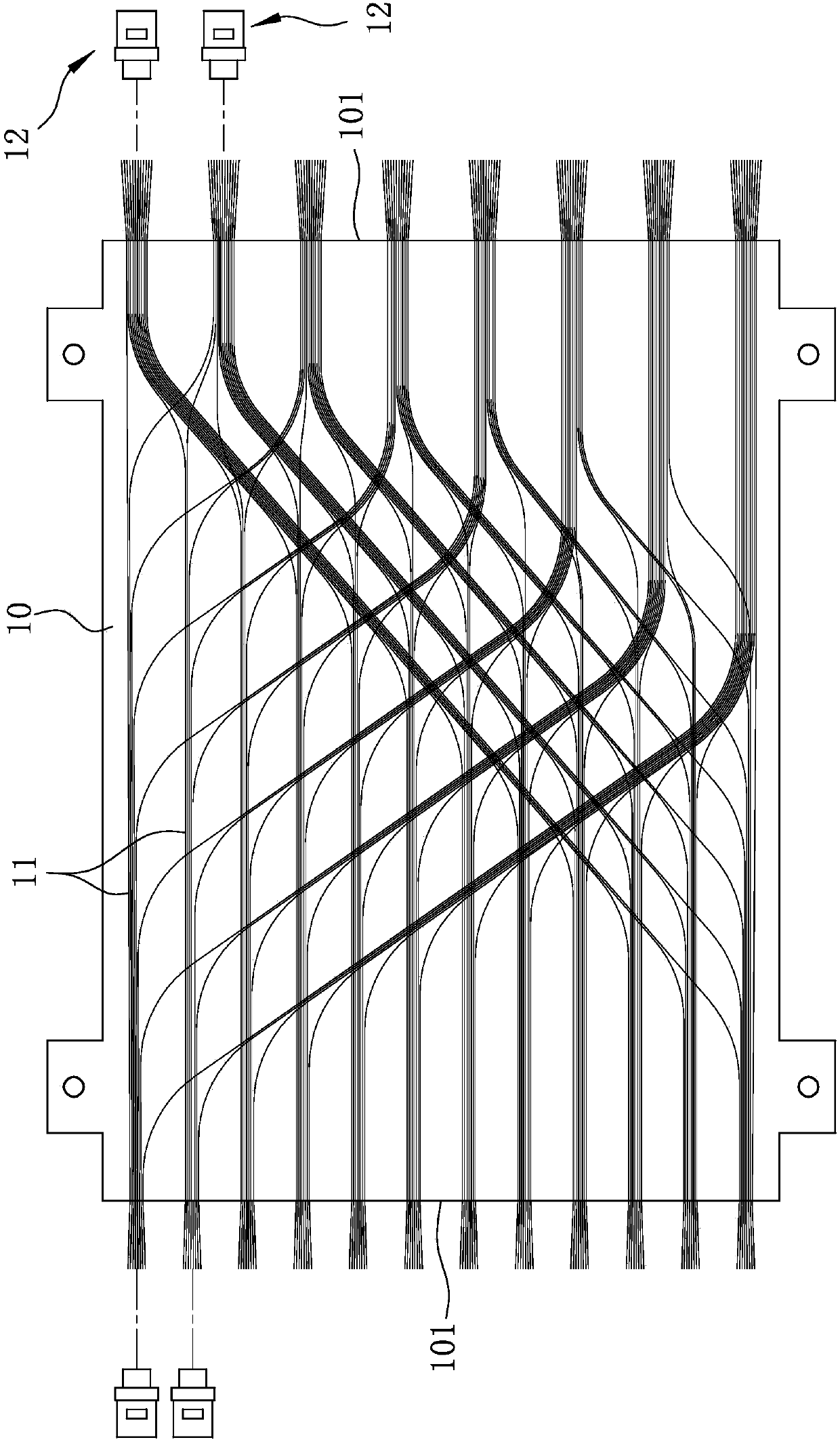
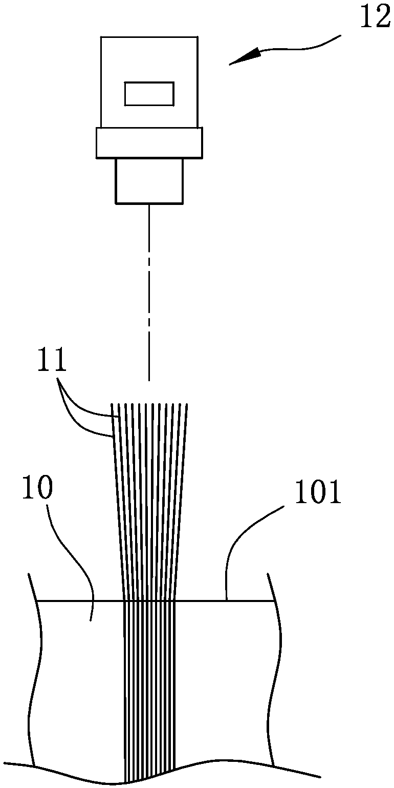
A technology of optical fiber lines and flexible boards, which is applied in the field of flexible board optical fiber line devices, and can solve the problems of easy bending of optical fibers 11, doubts about the bonding strength, and inability to be reliably threaded.

Inactive Publication Date: 2019-06-04
GLORIOLE ELECTROPTIC TECH CORP
View PDF3 Cites 0 Cited by
  • Summary
  • Abstract
  • Description
  • Claims
  • Application Information

AI Technical Summary

Problems solved by technology

[0003] refer to figure 2 Although the flexible plate optical path device has the above-mentioned advantages, since the optical fiber 11 is made of a soft material that is easy to bend, when a specific number of optical fibers 11 are to be threaded together on the corresponding assembly joint 12, due to the The optical fiber 11 is quite easy to bend after being stressed. If the optical fiber 11 is not properly aligned, or as long as any optical fiber 11 is bent, it cannot be reliably threaded. Therefore, it often takes repeated attempts to successfully thread the fiber 11.
In addition, because the optical fiber 11 is made of soft material, when the optical fiber 11 is passed through the joint 12, there is no supporting effect from other components, and the bonding strength is also quite doubtful.

Method used


Image

  • Flexible board optical fiber line device
  • Flexible board optical fiber line device
  • Flexible board optical fiber line device

Examples


Embodiment Construction

[0019] The present invention will be described in detail below in conjunction with the accompanying drawings and embodiments.

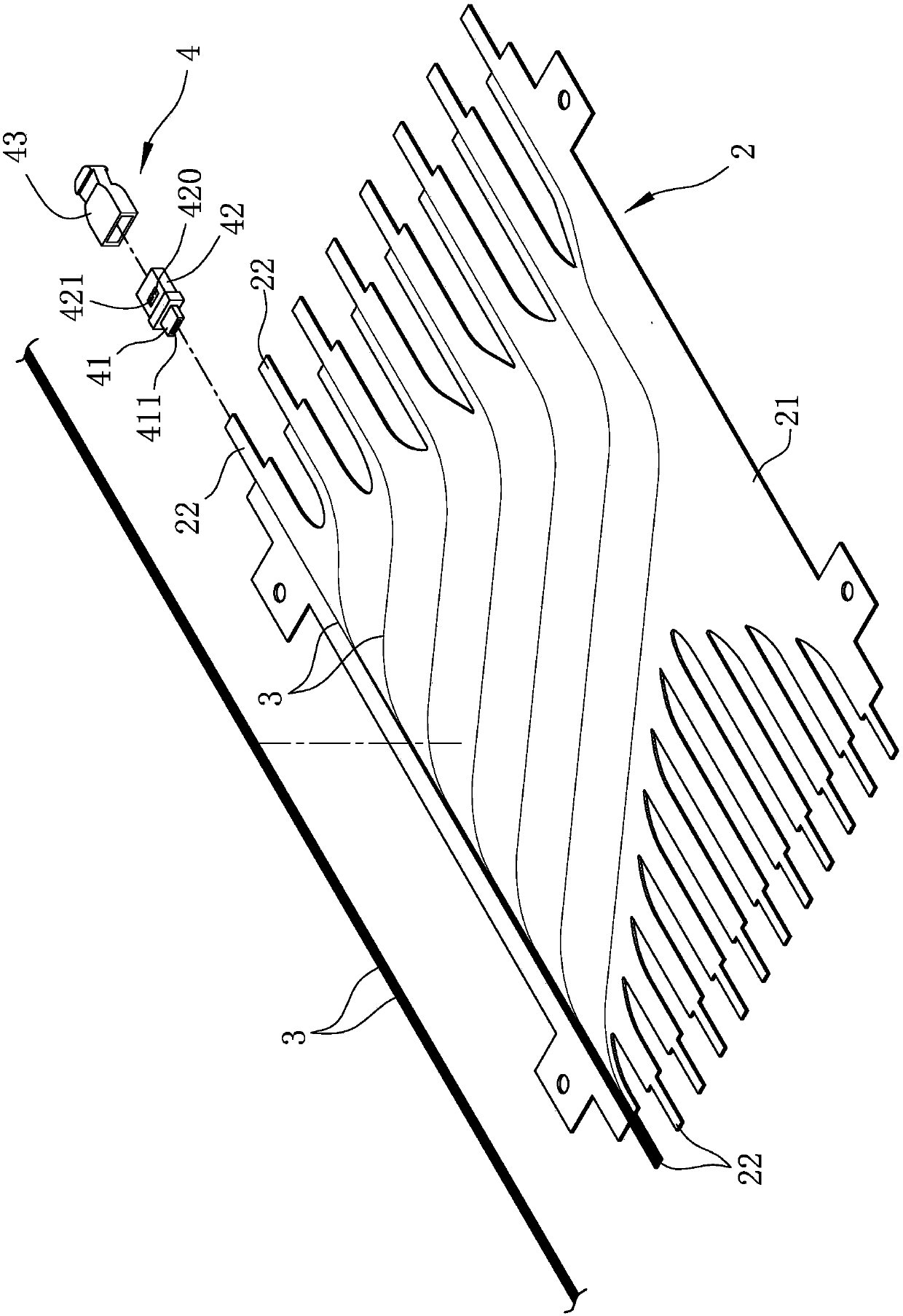
[0020] refer to image 3 , an embodiment of the flexible board optical fiber line device of the present invention, the embodiment includes a substrate 2 , a plurality of optical fibers 3 arranged on the substrate 2 , and a plurality of connector units 4 . The substrate 2 includes a main configuration portion 21 , and a plurality of support portions 22 extending outward from the main configuration portion 21 for a certain distance and spaced apart from each other. It should be explained firstly that the optical fiber 3 is mainly arranged in a specific network type on the main configuration part 21 according to a pre-designed path, and is fixed on the substrate 2 by spraying glue. However, since the method of laying the optical fiber 3 is not the main feature of the present invention, it will not be further described below.

[0021] refer to image 3...


PUM


Abstract

The invention discloses a flexible board optical fiber line device, which comprises a substrate, a plurality of optical fibers disposed on the substrate, and at least one connector unit, wherein the substrate comprises a main arrangement portion and at least one support portion extending outward from the main arrangement portion by a distance; the optical fibers are arranged according to a pre-arranged optical path and extend from the main arrangement portion to the at least one support portion; the at least one connector unit comprises a penetrating piece surrounding a penetrating hole; and the optical fiber and the support portion of the substrate together penetrate the penetrating hole of the penetrating piece. The optical fiber is supported through the support portion of the substrate,the optical fiber in the case of penetrating the penetrating piece can be prevented from being bent, and the making efficiency is effectively enhanced.

Description

technical field [0001] The invention relates to an optical fiber circuit device, in particular to a flexible board optical fiber circuit device. Background technique [0002] refer to figure 1 , is an existing flexible board optical path device, including an additional circuit board 10 with two end edges 101 respectively located on opposite sides, a plurality of strips are arranged on the additional circuit board 10 according to the design and protrude from two ends respectively. The optical fiber 11 at the end 101 and a plurality of joints 12 through which the optical fiber 11 passes. The flexible board optical path device can directly arrange the optical fiber 11 on the additional circuit board 10 with automatic setting. In addition to the yield and efficiency of 11, combined with the light and thin characteristics of the material of the additional circuit board 10, the modularization of the optical path can also be realized. As long as the group connector 12 is connecte...

Claims


Application Information

Patent Timeline
Patent Type & Authority Applications(China)
IPC IPC(8): G02B6/36G02B6/46
Inventor 许淑惠
Owner GLORIOLE ELECTROPTIC TECH CORP
Learn More