
Vortex station

A technology of vortex and air flow, applied in the field of vortex stations

Active Publication Date: 2019-06-04
AUCKLAND UNISERVICES LTD
View PDF6 Cites 2 Cited by
  • Summary
  • Abstract
  • Description
  • Claims
  • Application Information

AI Technical Summary

Problems solved by technology

However, it requires expensive vertical cylindrical walls around the site to create vortices

Method used


Image

  • Vortex station
  • Vortex station
  • Vortex station

Examples


Embodiment Construction

[0190] Throughout the specification, the same reference numerals will be used to refer to the same features in different embodiments.

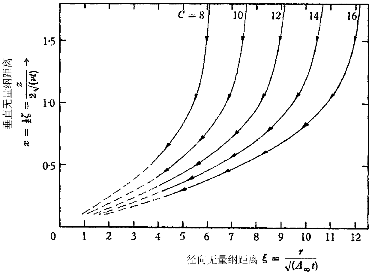
[0191] The inventors have developed improvements to traditional heat engine theory to allow improved prediction of vortex height and subsequent thermodynamic efficiency and wind speed in atmospheric buoyancy vortices by reconsidering the nature of the cold reservoir of the heat engine. Preliminary modeling suggests an economical and carbon-neutral approach to converting waste heat into electricity with an overall efficiency of about 5%. Embodiments of VCV or vortex stations capable of converting waste heat into electricity are provided and detailed below.

[0192]Because the VCV concentrates buoyancy at high wind speeds at or near ground level, the tall structures and costs of large turbines of the prior art are avoided. VCVs themselves can be very large and can be built at very low or significantly lower cost than prior art types of vortex g...


PUM


Abstract

This invention relates to a vortex station and method for producing a vortex similar to one of a group consisting of dust-devils and waterspouts. The apparatus comprises a ground platform forming a base for the vortex station, a plurality of vanes to direct an air flow into a vortex station and about the vortex station in a substantially swirling manner, at least one wind turbine disposed near thecentre of said vortex station, in a path of a concentrated air flow, wherein the movement of the air in the vortex station is such that an atmospheric buoyancy vortex is created in the centre of thevortex station, a supply of a working fluid (e.g. water) to the vortex station at or near the centre of the vortex station such that the air is of a saturated condition or an at least partially saturated condition with the working fluid (e.g. water), the working fluid (e.g. water) supplied at a sufficient quantity or amount so as to assist with maintaining buoyancy and stability of a vortex created.

Description

technical field [0001] The present invention relates to a vortex station in which a vortex-like convective vortex is generated from a heat source, such as a waste heat source, and this heat is converted into electrical energy. Background technique [0002] Many attempts have been made to harness waste heat to generate electricity, but the low power densities available at low temperatures make the equipment required in such processes prohibitively large and expensive. For "fuel-free" energy sources, capital and operating costs are key to economic viability, so the use of atmospheric buoyancy vortices as "virtual chimney vortices" (hereinafter referred to as VCVs) is attractive. Because VCVs concentrate buoyancy at high wind speeds at ground level, tall structures and the cost of large turbines are avoided. VCVs themselves can be very large and can be built at low cost. [0003] US 7086823 discloses such a vortex or vortex engine. However, it requires expensive vertical cyl...

Claims


Application Information

Patent Timeline
Patent Type & Authority Applications(China)
IPC IPC(8): F03D9/34
CPCF03D9/39Y02E10/728Y02B10/30F05B2240/132Y02E10/74Y02E10/72F03G7/00F03D3/005F03D3/061F05B2240/211F05B2240/30Y10T137/2104F05B2260/209F15C1/16F05B2240/3062Y10T137/2087F23R3/12F23R3/58F03D3/02Y02E10/70F03D9/34
Inventor N·A·霍克斯
Owner AUCKLAND UNISERVICES LTD
Learn More