
Housing for an electrical appliance

A technology for electrical equipment and housings, applied in the field of housings for electrical equipment

Active Publication Date: 2019-06-04
PILZ (COMPANY)
View PDF5 Cites 0 Cited by
  • Summary
  • Abstract
  • Description
  • Claims
  • Application Information

AI Technical Summary

Problems solved by technology

[0005] In both of the above-mentioned solutions, there is no possibility of detecting unauthorized disassembly of the housing and the holding device

Method used


Image

  • Housing for an electrical appliance
  • Housing for an electrical appliance
  • Housing for an electrical appliance

Examples


Embodiment Construction

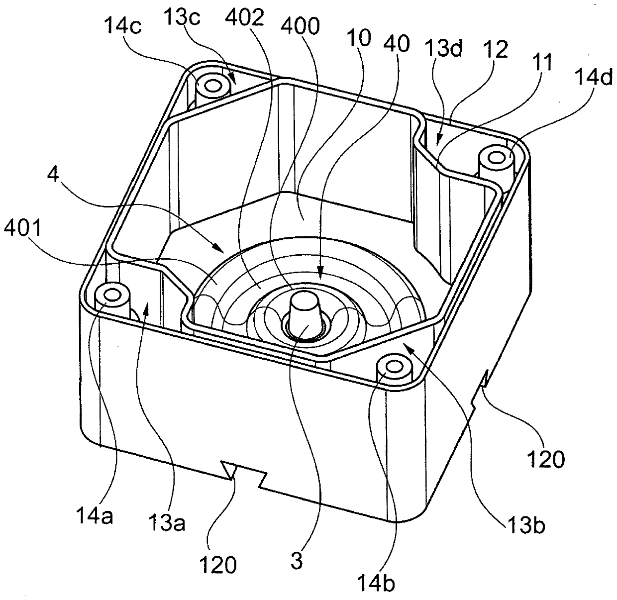
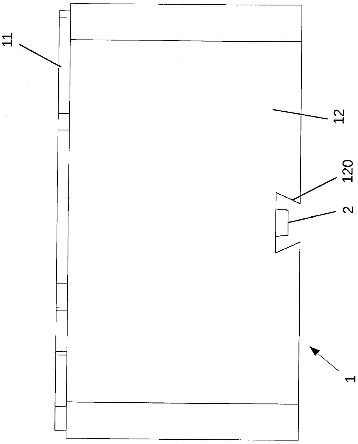
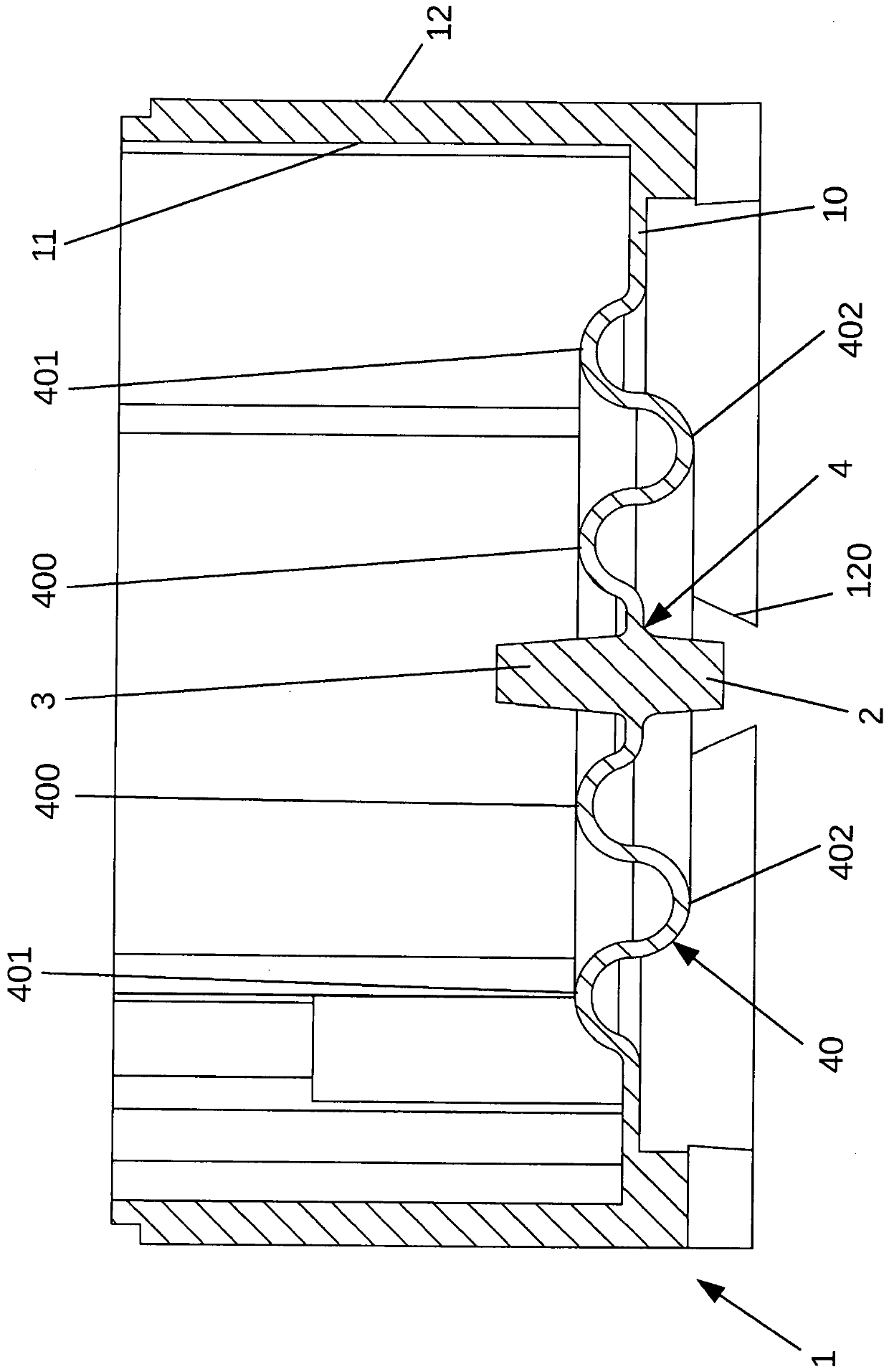
[0021] refer to Figures 1 to 4 A housing 1 for an electrical installation, such as an emergency stop device for a machine or a technical installation, comprises a housing bottom 10 , a surrounding inner housing wall 11 and a surrounding outer housing wall 12 . The housing 1 produced from plastic has a substantially rectangular, currently substantially square, contour. A surrounding (that is to say extending in the circumferential direction) inner wall 11 delimits the interior receiving space of the housing 1 , in which the components of the electrical appliance can be accommodated. Housing 1 can be closed by means of a housing cover likewise made of plastic and sealed in such a way that it achieves an increased degree of protection, in particular degree of protection IP65. The electrical connection can be realized, for example, by plugging in a five-pole M12 plug connection conventional in the industry.

[0022] as in figure 1 and 4 As can be seen in , the inner housing w...


PUM


Abstract

The invention relates to a housing (1) for an electrical appliance, comprising: a housing base (10), which has a connecting portion (4) for connecting the housing (1) to a machine, a technical apparatus or a building wall, and at least one fastening element (2), which is provided on an outer face of the connecting portion (4), wherein the fastening element (2) is designed such that said fasteningelement can be interlockingly and / or frictionally connected to a corresponding retaining element of the machine, the technical apparatus or the building wall, and wherein: the housing (1) can be closed by means of a housing cover; the connecting portion (4) is designed to be resiliently deformable and has, on an inner face, an unlocking element (3) which can be actuated by a user, is operatively connected to the fastening element (2) and is designed such that the unlocking element can only be actuated from the inside when the housing (1) is open, in order to release the interlocking and / or frictional connection of the fastening element (2) to the retaining element of the machine, the technical apparatus, or the building wall.

Description

technical field [0001] The invention relates to a housing for an electrical device, comprising a housing bottom with a connection section for connecting the housing to a machine, technical installation or on the wall of the building; and at least one fastening element, which is arranged on the outside of the connection section, wherein the fastening element is constructed such that the fastening element can be connected to the machine, technical installation or building The corresponding retaining element of the object wall is positively and / or non-positively connected, and the housing can be locked by means of a housing cover. Background technique [0002] Housings of the type mentioned at the outset are known from the prior art in various embodiments for electrical devices, which may be, for example, emergency stop devices for dangerous machines or technical installations. In particular in the case of housings for emergency stop devices, it is known, for example, to screw...

Claims


Application Information

Patent Timeline
Patent Type & Authority Applications(China)
IPC IPC(8): H02G5/00F03D80/80H01H9/02H01H9/04H01H13/06H02B1/052H05K5/02H02B1/40
CPCH01H9/02H01H9/04H01H13/06H02B1/40H05K5/0208Y02B10/30H05K5/0204H02B1/052H01H13/04
Inventor J·塞德T·汉佩
Owner PILZ (COMPANY)
Learn More