A kind of unmanned aerial vehicle electrostatic pollination device and method
A pollination device and unmanned aerial vehicle technology, which is applied to launch devices, botanical equipment and methods, aircraft parts, etc., can solve the problems of no harvest, high pollen consumption, high labor intensity, etc., so as to reduce the influence of other wind directions and improve pollination. Accuracy rate and the effect of improving pollination quality
- Summary
- Abstract
- Description
- Claims
- Application Information
AI Technical Summary
Problems solved by technology
Method used
Image
Examples
Embodiment 1
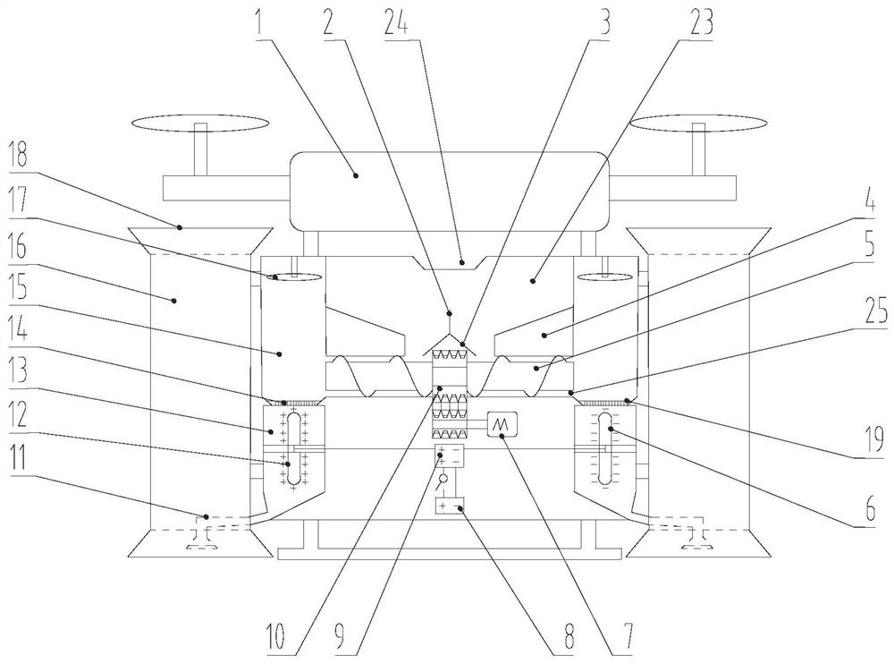
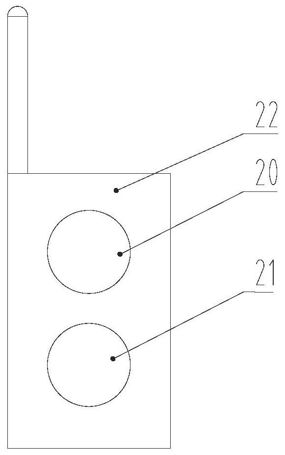
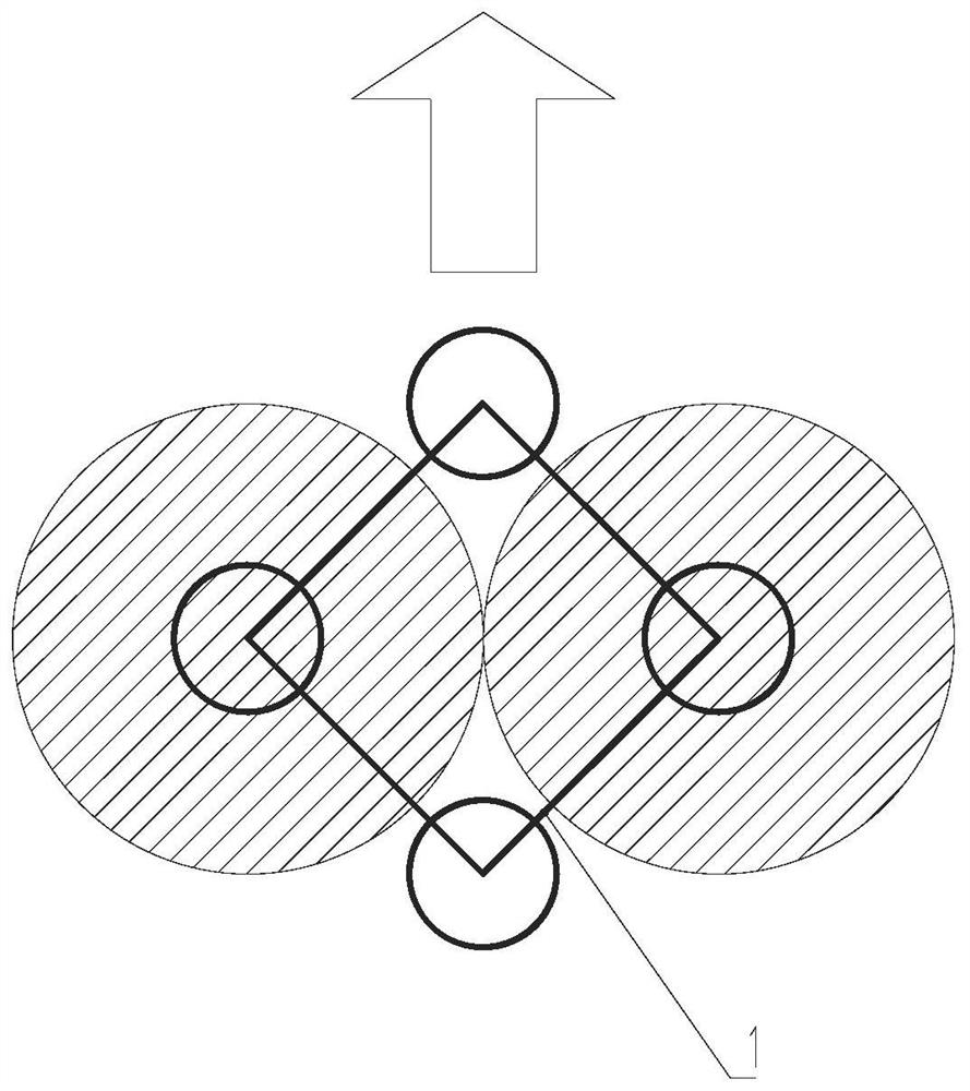
[0030] see Figure 1-Figure 7, an unmanned aerial vehicle electrostatic pollination device, comprising a rotor-type unmanned aerial vehicle 1, a powder spraying device and a remote controller 22, the top of the powder spraying device is connected with the bottom of the drone 1 body through a bracket, and the powder spraying device The device includes a pollen storage box 23, an atomization mechanism and a charging assembly; the atomization mechanism includes two atomization boxes 15, and the two atomization boxes 15 are respectively arranged on both sides of the pollen storage box 23, and the two atomization boxes The top of the box 15 is provided with an atomizing fan 17; the top of the pollen storage box is provided with a pollen supply port 24, and both sides are provided with a pollen outlet 25 communicating with the inner cavity of the atomization box 15, and the pollen storage The box 23 is provided with a pollen supply drive mechanism that transmits pollen to the two at...
Embodiment 2
[0045] see Figure 8 , The difference between this embodiment and Embodiment 1 is that a deflector assembly is provided in the air collector 16, and the deflector assembly includes a transverse deflector set 27 and a longitudinal deflector set 28, and the transverse deflector The baffle set 27 and the longitudinal baffle set 28 are arranged at intervals in the air collector 16 along the vertical direction.
Embodiment 3
[0047] see Figure 9-Figure 10 , The difference between this embodiment and Embodiment 1 is that a deflector assembly is provided in the air gathering tube 16, and the deflector assembly is composed of a plurality of annular deflector plates 29, and the plurality of annular deflector plates 29 are arranged along the gradually shrinks in the radial direction.
PUM
 Abstract
Description
Claims
Application Information
 - R&D
- Intellectual Property
- Life Sciences
- Materials
- Tech Scout
- Unparalleled Data Quality
- Higher Quality Content
- 60% Fewer Hallucinations
Browse by: Latest US Patents, China's latest patents, Technical Efficacy Thesaurus, Application Domain, Technology Topic, Popular Technical Reports.
© 2025 PatSnap. All rights reserved.Legal|Privacy policy|Modern Slavery Act Transparency Statement|Sitemap|About US| Contact US: help@patsnap.com


