
A stainless steel surface drawing treatment auxiliary device

A surface drawing and auxiliary device technology, which is applied in the direction of metal processing equipment, abrasive belt grinders, manufacturing tools, etc., can solve the problems of the influence of the service life of the drawing belt, increase the use cost of the drawing belt, and shorten the cooling time of the drawing belt. The effect of drawing cost, prolonging the service life and reducing the risk of corrosion

Active Publication Date: 2020-05-12
浙江德瑞不锈钢有限公司
View PDF7 Cites 0 Cited by
  • Summary
  • Abstract
  • Description
  • Claims
  • Application Information

AI Technical Summary

Problems solved by technology

However, when the drawing tape is drawing, the drawing width of the target stainless steel plate is fixed. When the drawing width changes, it is necessary to replace the drawing tape with different lengths, which seriously affects the work efficiency and increases the use cost of the drawing tape. In addition, the use of the drawing tape When the cooling time is too short, its surface is easily damaged due to high temperature, which will affect the service life of the drawing tape

Method used


Image

  • A stainless steel surface drawing treatment auxiliary device
  • A stainless steel surface drawing treatment auxiliary device
  • A stainless steel surface drawing treatment auxiliary device

Examples


Embodiment 1

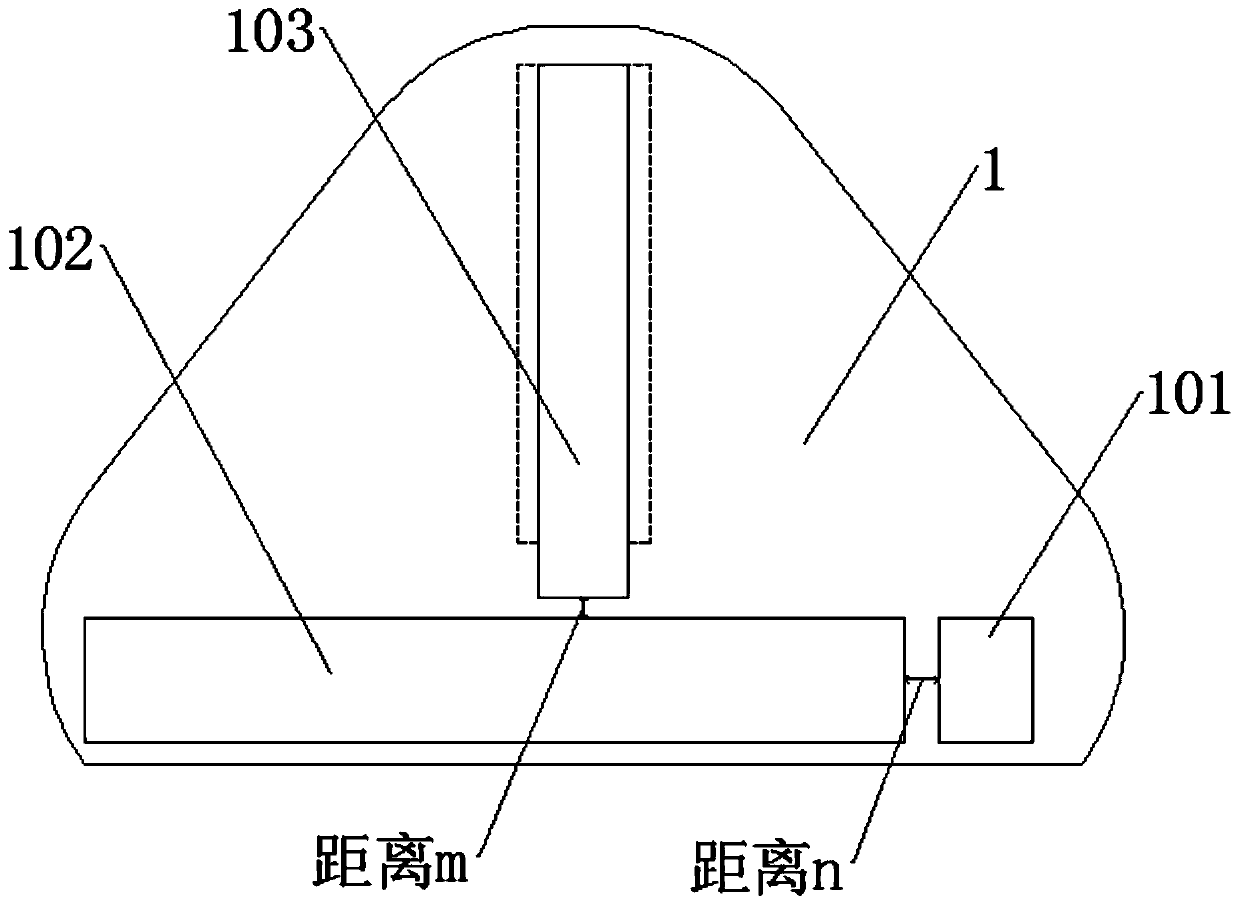
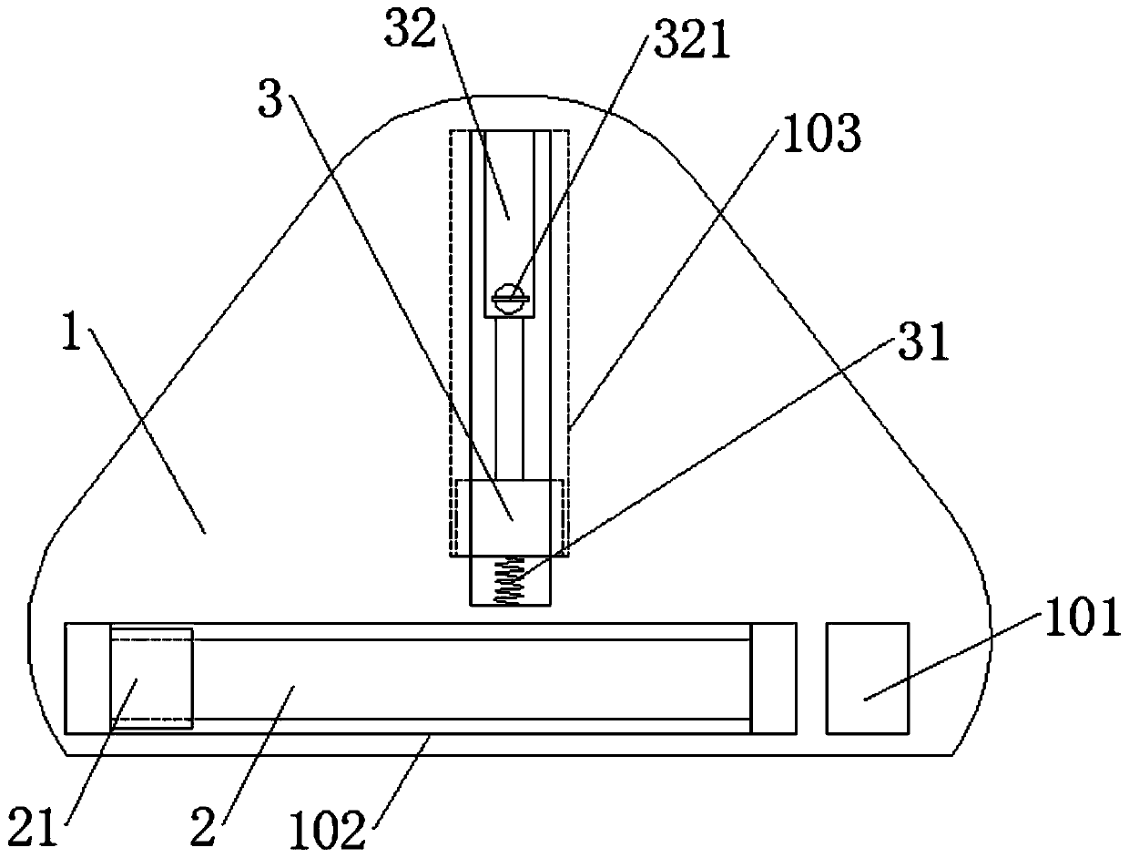
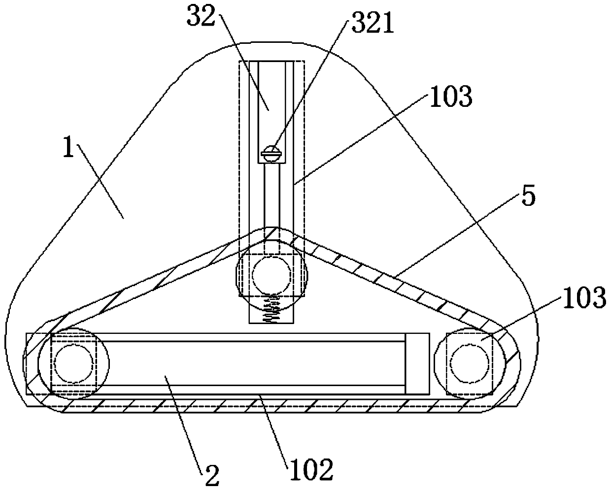
[0039] see Figure 1-6 , an auxiliary device for stainless steel surface drawing treatment, comprising a fixed bottom plate 1, the front end of the fixed bottom plate 1 is respectively excavated with a fixed groove 101, a movable horizontal groove 102 and a movable vertical groove 103, the fixed groove 101 and the movable horizontal groove 102 are arranged in parallel, and the movable horizontal groove 102 is arranged in parallel. Slot 102 and movable vertical groove 103 are arranged vertically, and electric slide table 2 is connected in movable horizontal groove 102, and slide block 21 is slidably connected on electric slide table 2, and movable block 3 is slidably connected in movable vertical groove 103, and movable block 3 and The inner top end of movable vertical groove 103 is connected with expansion link 32, is connected with locking knob 321 on the expansion link 32, and locking knob 321 is used for fixing the length of expansion link 32, and the inner end of fixing gro...


PUM


Abstract

The invention discloses an auxiliary device for stainless steel surface wire drawing treatment, and belongs to the field of stainless steel surface wire drawing. The auxiliary device for the stainlesssteel surface wire drawing treatment comprises a fixed bottom plate; a fixed groove, a movable transverse groove and a movable vertical groove are separately formed in the front end of the fixed bottom plate; the fixed groove and the movable transverse groove are formed in parallel; the movable transverse groove and the movable vertical groove are formed perpendicular to each other; the interiorof the movable transverse groove is connected with an electric sliding table; the electric sliding table is in sliding connection with a sliding block; the interior of the movable vertical groove is in sliding connection with a moving block; a telescopic rod is connected between the inner top ends of the moving block and the movable vertical groove; the telescopic rod is connected with a locking knob; the wire drawing width of a wire drawing band can be adjusted according to the width of a wire drawing stainless steel plate, so that the trouble of replacing the wire drawing band is reduced, the work efficiency is improved, and the wire drawing cost is reduced; and compared with the existing wire drawing band, the perimeter is remarkably increased, so that the cooling time of the wire drawing band is also prolonged, and the service life of the wire drawing band is effectively prolonged.

Description

technical field [0001] The invention relates to the field of stainless steel surface wire drawing, and more specifically relates to an auxiliary device for stainless steel surface wire drawing treatment. Background technique [0002] Metal finishing comes in many different forms, such as: sandblasting (creating a matte pearly silver finish), polishing (creating a mirror finish), embossing (pressing out various textures), electroplating (covering with a layer of other metal), spraying ( covering other non-metallic coatings), and brushed (to create a satin-like effect). Compared with other surface treatments, the brushed treatment can make the metal surface obtain a non-mirror-like metallic luster, which has a very strong decorative effect like silk satin, as if giving new vitality and life to ordinary metals, so the current brushed treatment has more More and more market recognition and wide application. [0003] Stainless steel surface brushing treatment is a surface treat...

Claims


Application Information

Patent Timeline
Patent Type & Authority Patents(China)
IPC IPC(8): B24B21/18B24B21/20
Inventor 不公告发明人
Owner 浙江德瑞不锈钢有限公司
Learn More