
Stirring device for plastic foam particle film coating dryer

A technology of stirring device and plastic foam is applied in the field of stirring device for plastic foam particle coated film dryer, which can solve the problems of small contact area between a stirring plate and the inner wall of a casing, increased maintenance cost, low production efficiency, etc. The effect of chemical production, improving production efficiency and high production efficiency

Pending Publication Date: 2019-06-07
青岛物界供应链科技有限公司
View PDF6 Cites 0 Cited by
  • Summary
  • Abstract
  • Description
  • Claims
  • Application Information

AI Technical Summary

Problems solved by technology

[0005] In the above-mentioned patent, first of all, each set of rotating shafts is evenly distributed with stirring plates in a cross shape. Although the above can be stirred evenly so that the coating liquid is evenly wrapped on the foam particles, the contact area between the stirring plates and the inner wall of the casing is small. It is difficult to clean the particles, curing agent, and mold agent adhered to the inner wall of the casing. If accumulated for a long time, it is very easy to produce the phenomenon of "shaft holding", and the shaft is stuck, which affects production efficiency and increases maintenance costs.
Secondly, the rotating shaft can only be stirred, and the particles cannot be pushed to the discharge port. Due to the different loads of each part, it is easy to cause uneven stirring, low production efficiency and low output.

Method used


Image

  • Stirring device for plastic foam particle film coating dryer
  • Stirring device for plastic foam particle film coating dryer
  • Stirring device for plastic foam particle film coating dryer

Examples


Embodiment Construction

[0022] The present invention will be described in further detail below in conjunction with the accompanying drawings and specific embodiments.

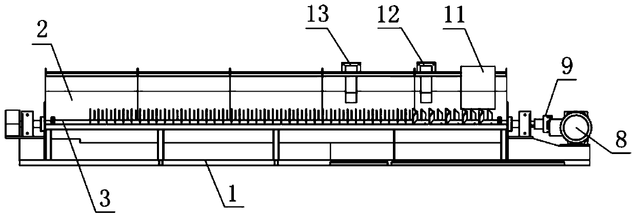
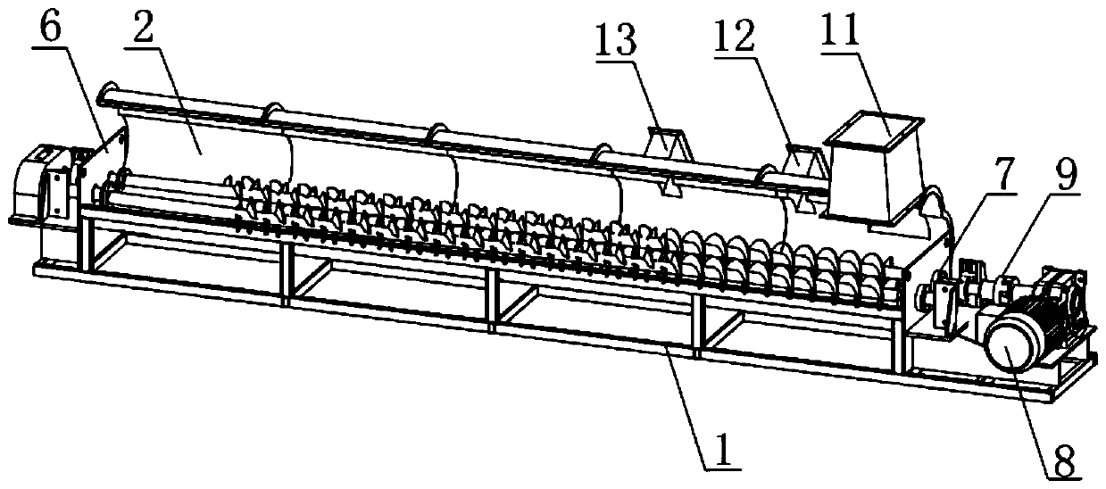
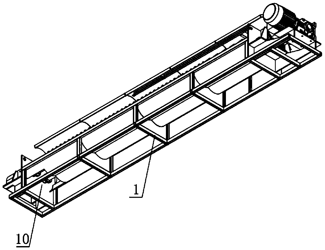
[0023] Such as Figure 1-5 As shown, the mixing device for the plastic foam particle coating dryer includes a frame 1 and a coating cavity 2 on the frame 1, and also includes a coating cavity 2 for mixing the particles with the coating solution. A stirring and rotating mechanism that performs uniform stirring and pushes particles to the discharging direction. The stirring and rotating mechanism includes a rotating shaft 3, on which a helical piece is spirally arranged along its axial direction, and the helical piece includes a continuous spiral for pushing particles to the discharging direction Sheet 4 and the intermittent spiral sheet for evenly stirring the pushed particles. The intermittent spiral sheet also has the function of assisting material pushing. The spiral sheet is divided into two parts: continuous spiral sheet and inter...


PUM


Abstract

The invention relates to the technical field of foam particle machining machines, in particular to a stirring device for a plastic foam particle film coating dryer. The stirring device comprises a machine frame and a film coating cavity arranged on the machine frame. The stirring device further comprises a stirring rotation mechanism which is arranged in the film coating cavity and used for uniformly stirring particles and film coating liquid and meanwhile pushing the particles in the discharging direction; the stirring rotation mechanism comprises a rotation shaft, and the rotation shaft is spirally provided with a spiral sheet in the axial direction of the rotation shaft; the spiral sheet comprises a continuous spiral sheet and a discontinuous spiral sheet, and the discontinuous spiral sheet is composed of a plurality of stirring fins at intervals in a spiral mode; in every two adjacent stirring fins, the left fin edge of one stirring fin and the right fin edge of the other stirringfin are arranged on the same line; and the outer side fin edges of the stirring fins are close to and tangent to the inner wall of the film coating cavity. The stirring device can stir and push materials in the discharging direction at the same time, continuous production is achieved, meanwhile, particles adhering to the inner wall of the film coating cavity can be scraped off, the production efficiency is high, the yield is large, and coating is uniform.

Description

technical field [0001] The invention relates to the technical field of foam particle processing machinery, in particular to a stirring device for a plastic foam particle film-coated dryer. Background technique [0002] Expanded Polystyrene (EPS for short), because EPS has good light weight and good thermal insulation effect, it is now widely used in the building insulation material industry. However, in recent years, due to the non-flammability of building insulation materials in various places, major fires have occurred continuously, causing huge losses in manpower and material resources, and the use of building insulation materials is facing a severe test. Therefore, it is necessary to add flame retardants to EPS raw materials In order to achieve the effect of flame retardancy. [0003] In the prior art, the EPS particles are foamed and cured first, then inorganic flame retardants and curing agents are added for mixing and stirring, and the resulting board is transforme...

Claims


Application Information

Patent Timeline
Patent Type & Authority Applications(China)
IPC IPC(8): B29B15/00B29B7/20B29B7/14B29B13/06
Inventor 刘庆杨徐嵩肖天宇彭国生
Owner 青岛物界供应链科技有限公司
Learn More