A powder tank of a coating machine

A technology of coating machine and powder tank, which is applied to the device and coating of surface coating liquid, which can solve the problems of wasting raw materials and affecting the working environment

Active Publication Date: 2017-02-08
KUNSHAN MICRO CAPACITORS ELECTRONICS
View PDF6 Cites 0 Cited by
  • Summary
  • Abstract
  • Description
  • Claims
  • Application Information

AI Technical Summary

Problems solved by technology

Since there is no special device for recovering the overflowed epoxy resin powder, the epoxy resin powder overflowed from the edge of the powder tank will be scattered under the machine table to be discarded or float in the air, affecting the working environment and wasting raw materials

Method used


Image

  • A powder tank of a coating machine

Examples


Embodiment Construction

[0016] The present invention will be specifically introduced below in conjunction with the accompanying drawings and specific embodiments.

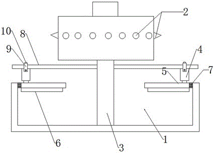
[0017] A powder tank 1 of a coating machine, comprising: an automatic powder feeder placed in the powder tank 1, a pin wheel 2 driven by a carrier paper tape, a turning machine 3 driven to rotate the pin wheel 2, placed on the turning machine 3 And connect the spilled powder recovery device on the inner wall of the powder tank 1; the spilled powder recovery device includes: a fixed rod 8 fixed on the rotating machine 3, a telescopic piece that is movably connected to the fixed rod 8, and is movably sleeved on the fixed rod 8 and fixed with a telescopic The connection assembly of the piece is fixed under the telescopic piece and scrapes the overflowing powder on the inner wall of the powder tank 1 back to the recovery piece that keeps the powder sticking position flush; It is an electromagnetic telescopic rod 4.

[0018] The connection as...


PUM


Abstract

The invention discloses a powder groove of a coating machine. The powder groove of the coating machine comprises an automatic powder feeding machine arranged in the powder groove, a pin wheel for driving a carrier paper tape to be conveyed, a rotary machine for driving the pin wheel to be rotated, and an overflowing powder recovery device arranged on the rotary machine and connected to the inner wall of the powder groove; the overflowing powder recovery device comprises a fixing rod fixed on the rotary machine, an elastic component moveably connected on the fixing rod, a connecting component moveably sleeved on the fixing rod and fixed with the elastic component, and a recovery component fixed under the elastic component and capable of scraping the overflowing powders of the inner wall of the powder groove and keeping the positions of adhered powders flush. The powder groove of the coating machine is capable of, according to the consumption of the powder materials, adjusting the positions of the recovered overflowing epoxy resin powders, and keeping the surfaces of the epoxy resin powders in the powder groove smooth and maintaining in the same horizontal plane; and the elastic component can be moved on the installing rod by the connecting component, so that the horizontal position of the recovery component can be adjusted, and the longitudinal position can be adjusted.

Description

technical field [0001] A coating processing equipment, especially a powder tank of a coating machine. Background technique [0002] In the production process of ceramic capacitors, it is necessary to first arrange the wires on the carrier paper tape and fix them with masking tape, and then drive the wires through the transmission carrier paper tape for subsequent wire bonding, inserting, soldering, and coating. , curing and other processing. Among them, the coating process is to adsorb epoxy resin on the surface of the capacitor body with ceramic chips welded at the end of the wire, so as to protect the capacitor body from damage and make the capacitor body moisture-proof. At the same time, it can withstand higher voltage shocks in use. The coating process is completed by using an automatic coating machine. First, a layer of epoxy resin is coated on the capacitor body through the powder tank, and then the capacitor carrier coated with epoxy resin is transported to the oven...

Claims


Application Information

Patent Timeline
Patent Type & Authority Patents(China)
IPC IPC(8): B05C19/06
CPCB05C19/06
Inventor 赵德星董加银赵光涛唐田赵光满
Owner KUNSHAN MICRO CAPACITORS ELECTRONICS
Why Eureka
Try Eureka