
A deep shaft support structure and construction method

A technology of support structure and construction method, which is applied in well sinking, earthwork drilling, vertical shaft equipment, etc., can solve the impact of ground pressure disaster, the failure of reasonable adjustment and release of concentrated stress of surrounding rock, and the increase of engineering cost and construction period of support structure. and other problems, to achieve the effect of uniform force distribution and reduction of bending stress

Active Publication Date: 2020-10-02
CINF ENG CO LTD
View PDF15 Cites 0 Cited by
  • Summary
  • Abstract
  • Description
  • Claims
  • Application Information

AI Technical Summary

Problems solved by technology

[0003] Another problem that the deep shaft support structure needs to face is high ground stress and rock burst. Blindly increasing the stiffness and strength of the support structure will not only increase the project cost and construction period, but also cause the concentrated stress of the surrounding rock to be adjusted and released without reasonable adjustment. It is easy to cause rock burst disasters

Method used


Image

  • A deep shaft support structure and construction method

Examples


Embodiment Construction

[0033] The present invention will be described in detail below with reference to the accompanying drawings and examples. It should be noted that, in the case of no conflict, the embodiments of the present invention and the features in the embodiments can be combined with each other. For the convenience of description, if the words "up", "down", "left" and "right" appear in the following, it only means that the directions of up, down, left and right are consistent with the drawings themselves, and do not limit the structure.

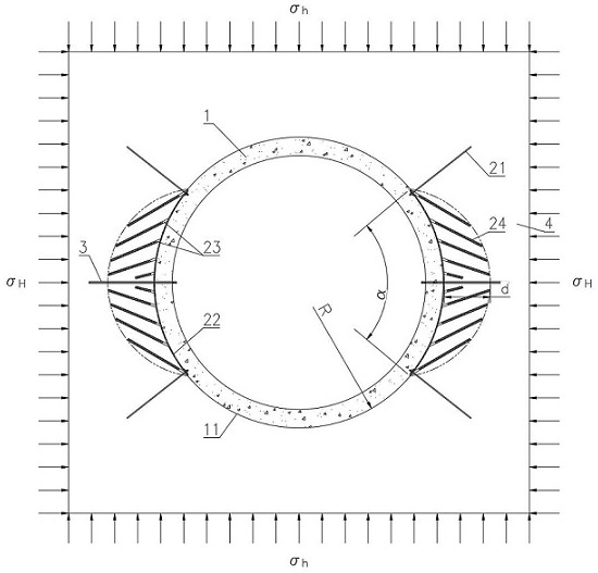
[0034] Such as figure 1 As shown, the deep shaft support structure provided by this embodiment is used for constructing a shaft excavation section 11 on the surrounding rock 4 and pouring to form the support of the shaft wall 1 . The deep shaft support structure includes anchor net fixing area, drilling group 23 and static breaking agent 24 . The anchor net fixing area is formed by the maximum horizontal stress σ on the shaft excavation section 11 H On...


PUM


Abstract

The invention provides a deep vertical well supporting structure. The deep vertical well supporting structure comprises anchor net fixing areas, drilled hole groups and static crushing agents, whereinthe anchor net fixing areas are symmetrically arranged on the wellbore tunneling section in the maximum horizontal stress direction, the drilled hole groups are formed in the mode of extending from the anchor net fixing areas into surrounding rock, and the drilled hole groups are filled with the static crushing agents; the anchor net fixing areas comprise anchor nets and anchor rods for fixing the anchor nets; and the anchor rods, the anchor nets, the drilled hole groups and the static crushing agents are combined to form a crescent in-situ yielding arch structure which is closely attached tothe position between the well wall and the surrounding rock. Compared with the relevant technology, the deep vertical well supporting structure utilizes the characteristics of being prone to extrusion and deformation during bearing force of the in-situ yielding arch structure to sufficiently mobilize the self-bearing ability of the deep part of the surrounding rock in the maximum horizontal stress direction, thus the radial load of the well wall in the maximum main stress direction is reduced, and bending stress generated in the well wall due to non-uniform horizontal confining pressure is reduced. The invention further provides a construction method of the deep well supporting structure.

Description

technical field [0001] The invention relates to the technical field of mine shaft support, in particular to a support structure and a construction method suitable for deep shafts with non-uniform horizontal confining pressure and high ground stress environments. Background technique [0002] With the depletion of shallow resources in my country, mine shafts in China have gradually entered the depth range of 1500-2000m. The support structure of the deep bedrock section is very different from the surface soil section and the shallow bedrock section. The non-uniform horizontal confining pressure is a factor that cannot be ignored in the failure of the deep shaft wall. In view of the in-situ stress environment of non-uniform horizontal confining pressure in the bedrock section of deep wells, the section of deep shafts is still mainly circular at present, and the well wall structure adopted is still based on reinforced (steel fiber) (steel plate) concrete structures with uniform ...

Claims


Application Information

Patent Timeline
Patent Type & Authority Patents(China)
IPC IPC(8): E21D20/00E21D21/00E21D5/04E21D5/11E21D1/03
Inventor 汪小东朱志根付宗智
Owner CINF ENG CO LTD
Learn More