Up-lock reliability test device capable of realizing lock ring horizontal position adjustment

A technology of lateral position and test device, which is used in the testing of measuring devices, transmission devices, mechanical parts, etc., can solve the problems of artificial adjustment of the lateral position of the lock ring, low overall stiffness, etc., and achieves light weight, small size, easy operation. handy effect

Active Publication Date: 2017-08-22
NORTHWESTERN POLYTECHNICAL UNIV
View PDF8 Cites 4 Cited by
  • Summary
  • Abstract
  • Description
  • Claims
  • Application Information

AI Technical Summary

Problems solved by technology

[0006] The purpose of the present invention is to solve the problem that the overall rigidity of the existing aircraft uplock test device is low and the lateral position of the lock ring cannot be adjusted artificially, and a reliability test device for the uplock that can realize the lateral position adjustment of the lock ring is provided.

Method used


Image

  • Up-lock reliability test device capable of realizing lock ring horizontal position adjustment
  • Up-lock reliability test device capable of realizing lock ring horizontal position adjustment
  • Up-lock reliability test device capable of realizing lock ring horizontal position adjustment

Examples


specific Embodiment approach 1

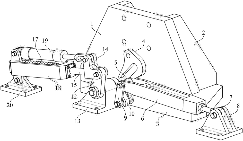
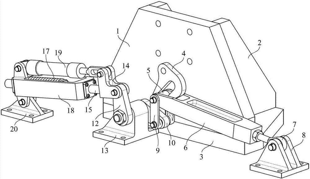
[0027] Specific implementation mode one: the following combination Figure 1 to Figure 9 Describe this embodiment, the upper lock reliability test device that can realize the lateral position adjustment of the lock ring described in this embodiment, it includes a support stand, it also includes a lock ring module, a crank module and a loading drive module;

[0028] The uplock is installed on the supporting platform, and the lock ring module, the crank module and the loading drive module are arranged under the uplock;

[0029] The support stand includes an upper lock installation plate 1, a reinforcing plate 2 and a base plate 3, the upper position lock installation plate 1 is vertically installed on the base plate 3, and the reinforcement plate 2 is fixedly connected to the side of the upper position lock installation plate 1 and fixed on the base plate 3; the upper position The lock is installed on the upper lock mounting plate 1;

[0030] The lock ring module includes a loc...

specific Embodiment approach 2

[0042] Specific implementation mode two: the following combination Figure 8 with Figure 9 Describe this embodiment, this embodiment will further explain Embodiment 1, there are steps at both ends of the rotating shaft 11, the No. 1 crank 10 and the No. 2 crank 12 are respectively connected to the low steps on both sides of the rotating shaft 11, and are locked by mounting nuts; The No. 1 crank 10 and the No. 2 crank 12 are fixed with the rotating shaft 11 through flat keys or splines.

[0043] Figure 8 with Figure 9 As shown, there are steps at both ends of the rotating shaft 11 for installing the No. 1 crank 10 and the No. 2 crank 12. There are threads on the outside of the steps for installing nuts, thereby locking the two cranks. The two cranks are fixed with the rotating shaft 11 through flat keys or splines. The rotating shaft 11 is installed in the shaft hole on the crank support 13 in a horizontal manner.

specific Embodiment approach 3

[0044] Specific implementation mode three: the following combination Figure 8 This embodiment will be described. This embodiment will further describe Embodiment 1 or 2. The included angle between the No. 1 crank 10 and the No. 2 crank 12 is 120°.

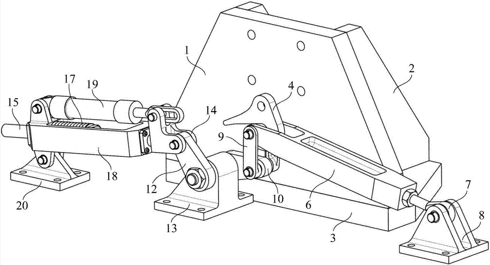
[0045] In order to prevent the No. 2 crank 12 from interfering with the screw joint 14 during the movement, an included angle of 120° is set between the No. 1 crank and the No. 2 crank. The connecting rod 9 is installed between the lock ring 5 and the number one crank 10 .

[0046] During the use of the test device in the test process, by screwing in or out the lock ring adjusting rod 7, the radius of the lock ring 5 swinging up and down can be adjusted and controlled, thereby adjusting the lateral position of the lock ring 5. During the adjustment of the lateral position of the lock ring 5, since the lock ring adjustment rod 7 is connected to the rocker support 8 through a pin, the rotation angle of the lock ring adjustment rod ...


PUM


Abstract

The invention provides an up-lock reliability test device capable of realizing lock ring horizontal position adjustment, belongs to the technical field of aviation equipment up-lock reliability test, and aims at solving the problems that the present aircraft up-lock test device has low integral rigidity and cannot realize manual adjustment of the lock ring horizontal position. The up-lock is a test piece and is installed on a supporting rack. A lock ring module, a crank module and a loading driving module are arranged below the up-lock and fixed on the surface of a vibration table through a support respectively. The lock ring module is used for simulating upward and downward movement of the lock ring under the real situation and can realize adjustment of the lock ring horizontal position. The loading driving module is used for driving the lock ring to upward and downward move and loading working load on the up-lock through the lock ring module. The crank module is arranged between the lock ring module and the loading driving module and used for transmitting the movement and the load of the loading driving module to the lock ring module. The up-lock reliability test device is used for reliability testing of the up-lock.

Description

technical field [0001] The invention relates to an uplock reliability test device capable of realizing the lateral position adjustment of a lock ring, and belongs to the technical field of aviation equipment uplock reliability tests. Background technique [0002] The uplock is an important part of the aircraft. It not only exists in the traditional mechanisms such as landing gear, landing gear door, and rear cargo door of the transport aircraft, but also in some new mechanisms, such as the lift fan door mechanism of the F-35, the X- The cargo compartment door mechanism of the 37B aerospace plane, etc. The uplock is used to lock or unlock various moving mechanisms on the aircraft. Once it fails, it is easy to cause the failure of the aircraft mission, or even serious accidents such as aircraft crash. Therefore, the reliability of the upper lock is the key content that aircraft designers pay attention to. In order to evaluate the reliability index of the aircraft uplock, exp...

Claims


Application Information

Patent Timeline
Patent Type & Authority Applications(China)
IPC IPC(8): G01M13/00F16H21/18
CPCF16H21/18G01M13/00
Inventor 孙中超庄新臣喻天翔崔卫民宋笔锋张玉刚
Owner NORTHWESTERN POLYTECHNICAL UNIV
Why Eureka
Try Eureka