Bearing assembly

a technology for bearings and turbomachines, which is applied in the direction of bearings, shafts, applications, etc., can solve the problems of poor axial load absorption and difficulty in mounting the rotor assembly to the frame, and achieve the effects of reducing the radial load of the bearing, avoiding the skid of the first bearing, and shortening and stiffening the rotor assembly

Active Publication Date: 2014-10-21
DYSON TECH LTD
View PDF72 Cites 4 Cited by
  • Summary
  • Abstract
  • Description
  • Claims
  • Application Information

AI Technical Summary

Benefits of technology

[0005]By providing an o-ring seat at an end of the bearing assembly, mounting the bearing assembly within a frame is made relatively easy. In particular, the bearing assembly can be inserted axially such that the o-ring pushes against a similar seat in the frame.
[0006]Providing an o-ring seat at an end of the bearing assembly has the further advantage that axial forces may be better opposed. In particular, the seats in the sleeve and the frame may extend around the o-ring such that axial displacement of the bearing assembly relative to the frame acts to compress the o-ring.
[0007]The sleeve may be adhered to the first bearing or the sleeve may form a clearance fit with the first bearing. This then has the advantage that the first bearing is able to move relative to the sleeve should the first bearing be subject to an axial force. The first bearing may comprise an inner race and an outer race, and the axial force may cause the inner race to move relative to the outer race. Since the sleeve is adhered or forms a clearance fit with the first bearing, the outer race is free to move relative to the sleeve. Consequently, in response to the movement of the inner race, the spring is able to displace the outer race relative to the sleeve so as to maintain the preload of the first bearing. When the sleeve is adhered to the first bearing, the elasticity of the adhesive join is sufficient to permit the first bearing to move relative to the sleeve in response to the axial force.
[0012]The shaft may comprise a stepped section and each of the bearings may abut the stepped section such that the bearings are spaced by a predetermined distance. Since the bearings are spaced by a predetermined distance, better control over the preload of bearings may be achieved. In particular, by employing a spring having a predetermined spring constant, each of the bearings may be preloaded with the same predetermined force.
[0014]The rotor assembly may comprise an impeller mounted to the shaft, the impeller generating in use an axial thrust in a direction from the second bearing to the first bearing, and the first bearing moves relative to the sleeve in response to the axial thrust. By moving relative to the sleeve, the preload of the first bearing may be maintained and thus skidding of the first bearing may be avoided.
[0015]The bearing assembly may project axially into a region bounded by the top and bottom of the impeller. As a result, a shorter and stiffer rotor assembly is achieved. Additionally, radial loading of the bearings is reduced owing to the shorter cantilever length between the impeller and the bearing assembly.

Problems solved by technology

Since the o-ring is formed of an incompressible material, it is generally difficult to mount the rotor assembly to the frame.
Additionally, although the mounting may provide good absorption of radial loads, the mounting is generally poor at absorbing axial loads.

Method used


Image

  • Bearing assembly
  • Bearing assembly
  • Bearing assembly

Examples


Embodiment Construction

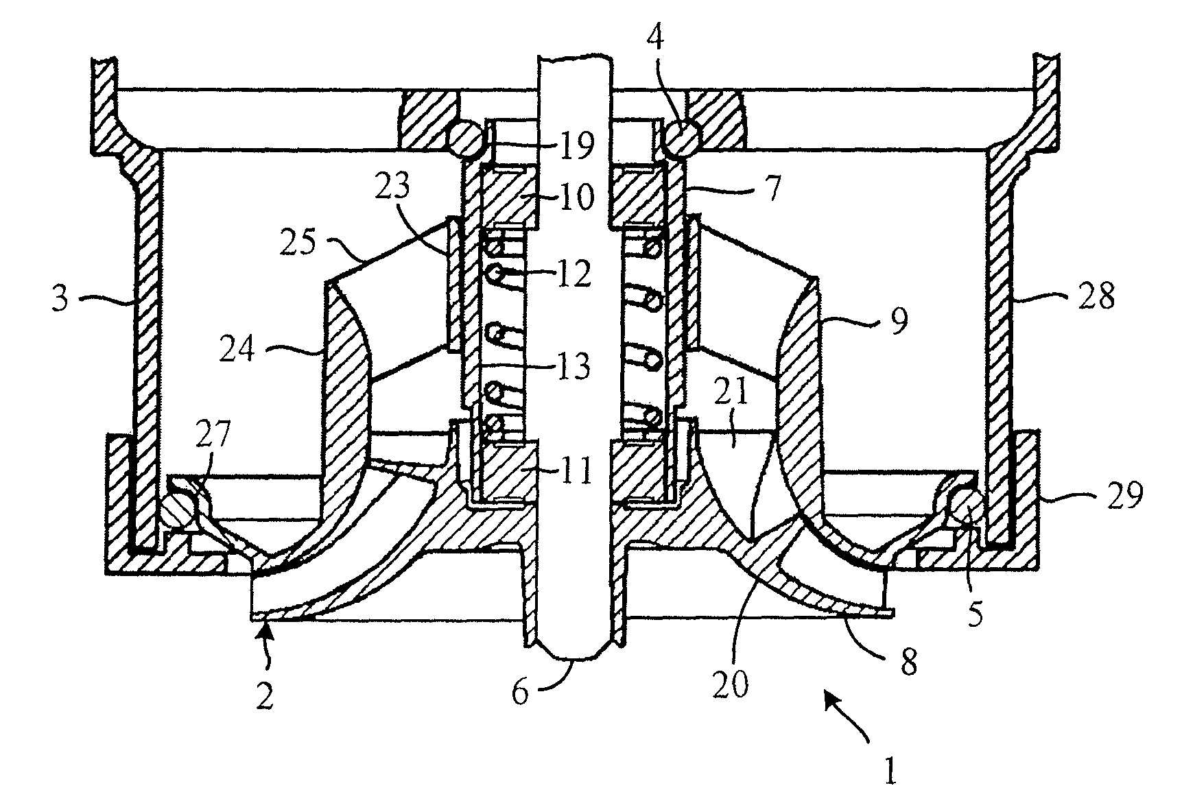
[0020]The turbomachine 1 of FIGS. 1 to 3 comprises a rotor assembly 2 mounted to a frame 3 by a pair of o-rings 4,5.

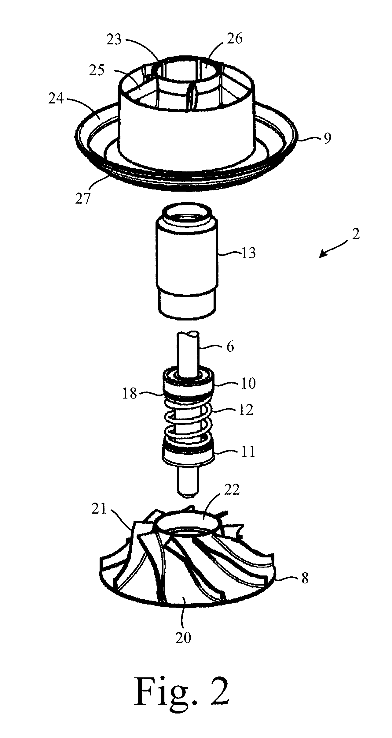
[0021]The rotor assembly 2 comprises a shaft 6, a bearing assembly 7, an impeller 8 and a shroud 9. The bearing assembly 7 and the impeller 8 are mounted to the shaft 6, and the shroud 9 is mounted to the bearing assembly 7 so as to cover the impeller 8.

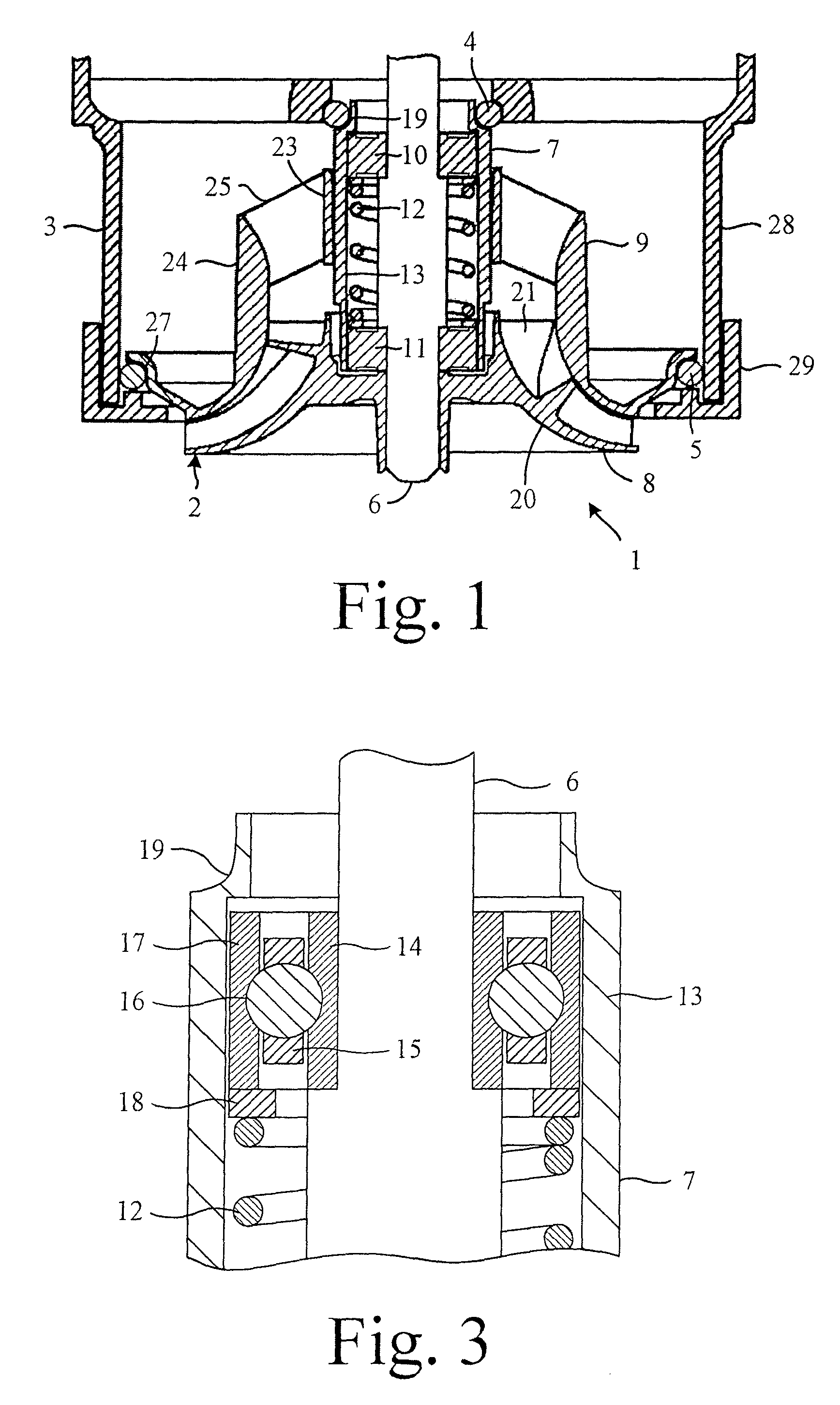
[0022]The bearing assembly 7 comprises a first bearing 10, a second bearing 11, a spring 12, and a sleeve 13.

[0023]Each of the bearings 10,11 comprises an inner race 14, a cage 15 supporting a plurality of balls 16, and an outer race 17. The bearings 10,11 are mounted to the shaft 6 on opposite sides of a stepped section. The inner race 14 of each bearing 10,11 abuts the stepped section, which serves to space the two bearings 10,11 by a predetermined length.

[0024]The spring 12 surrounds the stepped section of the shaft 6 and applies an axial force to the outer races 17 of the two bearings 10,11. Owing to the relative si...


PUM


Abstract

A bearing assembly that includes a first bearing, a second bearing, a spring and a sleeve. The spring applies a preload to each of the bearings, and the sleeve surrounds the spring and the bearings. The sleeve includes an end portion that extends axially beyond the first bearing. The end portion includes a step down in the outer diameter that defines a seat for an o-ring.

Description

REFERENCE TO RELATED APPLICATIONS[0001]This application claims the priority of United Kingdom Application No. 1114787.3, filed Aug. 26, 2011, the entire contents of which are incorporated herein by reference.FIELD OF THE INVENTION[0002]The present invention relates to a bearing assembly for a turbomachine.BACKGROUND OF THE INVENTION[0003]The rotor assembly of a turbomachine may include a bearing assembly that is soft-mounted to a frame by an o-ring. The o-ring may be seated in a groove formed around the bearing assembly. Since the o-ring is formed of an incompressible material, it is generally difficult to mount the rotor assembly to the frame. Additionally, although the mounting may provide good absorption of radial loads, the mounting is generally poor at absorbing axial loads.SUMMARY OF THE INVENTION[0004]In a first aspect, the present invention provides a bearing assembly comprising a first bearing, a second bearing, a spring applying a preload to each of the bearings, and a sle...

Claims


Application Information

Patent Timeline
Patent Type & Authority Patents(United States)
IPC IPC(8): F16C19/54F16C27/06F16C35/077F16C25/08F16C35/06F04D29/04
CPCF16C35/06F16C2360/44F16C19/54F16C27/066F16C25/083F16C19/548F16C35/077F04D29/059A47L9/0455A47L9/1691A47L9/22F16C19/14
Inventor CHILDE, MATTHEW JOHNBURLINGTON, GEOFFREY MICHAELJONES, DAVID MICHAEL
Owner DYSON TECH LTD
Why Eureka
Try Eureka