Engine oil control valve with guiding structure

A technology of oil control valve and guide structure, which is applied to non-mechanically actuated valves, valve devices, mechanical equipment, etc. Reduced load, reduced friction and wear, reduced wear effects

Active Publication Date: 2015-03-25
MIANYANG FULIN PRECISION MACHINING
View PDF5 Cites 4 Cited by
  • Summary
  • Abstract
  • Description
  • Claims
  • Application Information

AI Technical Summary

Problems solved by technology

[0003] The movement of the magnetic core in some existing oil control valves is completely supported by the guide sleeve. During the working process of the oil control valve with guide structure, the inclination of the spring, the valve core, and the dif

Method used


Image

  • Engine oil control valve with guiding structure
  • Engine oil control valve with guiding structure
  • Engine oil control valve with guiding structure

Examples


Embodiment 1

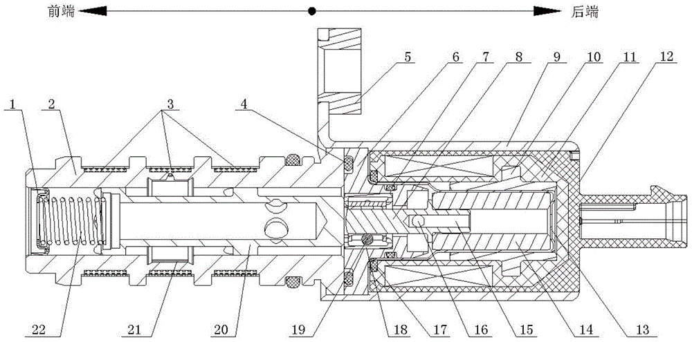
[0028] Such as figure 1 The shown oil control valve with guiding structure mainly includes spring seat 1, valve sleeve 2, pole shoe 6, magnetic core shaft 8, valve housing 9, electromagnetic solenoid assembly 12, magnetic core 14 and valve core 20 and a one-way valve 21, wherein the electromagnetic solenoid assembly 12 includes a skeleton 11 and a back yoke sleeve 10, the spring seat 1 is fixedly connected with one end of the valve sleeve 2, and the other end of the valve sleeve 2 is fixedly connected with the valve casing 9, The valve core 20 is installed in the inner cavity of the valve sleeve 2, and a spring 22 is arranged between the valve core 20 and the spring seat 1; They are respectively fixedly connected to both ends of the inner chamber of the valve housing 9, and an elastic washer 17 is arranged between the larger end of the pole shoe 6 and the skeleton 11 on the electromagnetic solenoid assembly 12. The main function of the elastic washer 17 is Prevent the electro...

Embodiment 2

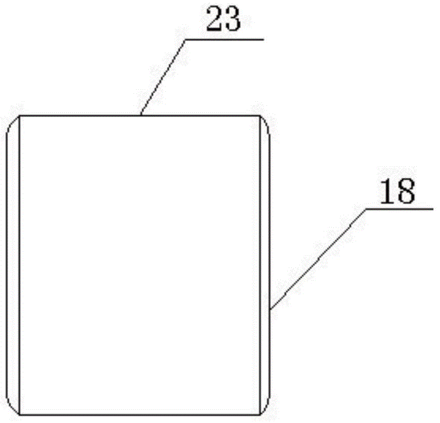
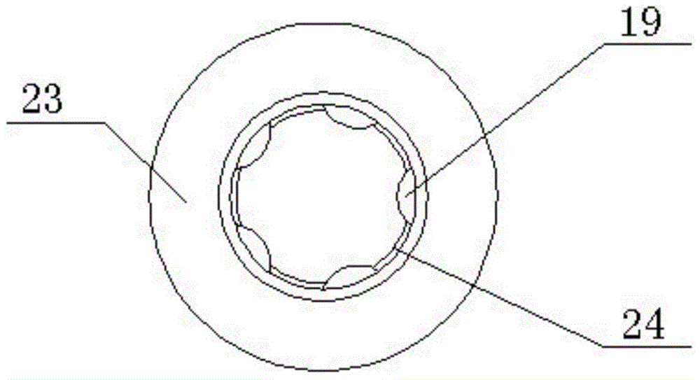
[0032]The difference from Embodiment 1 is that the bearing sleeve 23 of the first guide bearing 18 is omitted, and the ball 19 is arranged directly in the pole shoe 6 . Specifically, as Image 6 , Figure 7 As shown, a number of guide grooves 26 arranged circumferentially along the tail end of the pole shoe 6 are provided at the relatively large end of the pole piece 6, and balls 19 that can roll axially along the guide groove 26 are installed in the guide groove 26, and pass through The bottom plane of the guide groove 26 and the end surface of the tail end of the pole shoe 6 are riveted to limit the axial movement stroke of the ball 19 . The magnetic core 14 is supported on the guide sleeve 13 and is supported on the ball 19 through the front end of the magnetic core shaft 8 . In this way, when the magnetic core 14 moves axially under the drive of electromagnetic force and spring force, the magnetic core 14 is supported and guided by the guide sleeve 13 and forms sliding f...

Embodiment 3

[0035] Different from the above-mentioned embodiment 1 and embodiment 2, as Figure 8 , Figure 9 As shown, a second guide bearing is set between the magnetic core shaft 8 and the guide sleeve 13, and the open end of the guide sleeve 13 extends to the outside of the larger end of the pole piece 6. The structure of the second guide bearing is as follows Figure 10 , Figure 11 As shown, it includes a bearing frame 27 and a ball 19. The main part of the bearing frame 27 is ring-shaped, and several guide grooves 25 are provided on it. One end of the bearing frame 27 protrudes from several rings. The main part of the bearing frame 27 is evenly distributed in the circumferential direction. The L-shaped claws 28 are used to ensure that the bearing frame 27 is evenly stressed in the axial direction. The ball 19 is installed in the guide groove 25 and can roll axially along the guide groove 25 , and its axial rolling stroke is the axial length of the guide groove 25 . A ring groove...


PUM


Abstract

The invention provides an engine oil control valve with a guiding structure. The engine valve control valve comprises a valve element (20), a pole shoe (6), a magnetic core shaft (8), a magnetic core (14) and an electromagnetic solenoid assembly (12). A guiding sleeve (13) is arranged between the magnetic core (14) and a rear yoke sleeve (10) on the electromagnetic solenoid assembly (12), the magnetic core shaft (8) is fixedly connected with the magnetic core (14), the guiding structure with balls (19) is arranged between the magnetic core shaft (8) and the pole shoe (6), sliding friction is adopted between one end of the magnetic core (14) and the guiding sleeve (13), and rolling friction is adopted between the other end of the magnetic core (14) and the balls (19) through the magnetic core shaft (8). A stressed supporting point of the magnetic core can be transferred to the balls, the length of the arm of force of the acting force of the valve element to the magnetic core shaft is reduced, radial loads borne by the magnetic core and the guiding sleeve on the right side of the balls are reduced, abrasion of the magnetic core and the guiding sleeve is effectively lowered, and the service life of the engine oil control valve is effectively prolonged.

Description

technical field [0001] The invention relates to the technical field of engine oil control valves, in particular to an engine oil control valve with a guide structure used in a variable valve timing system of an engine. Background technique [0002] The variable valve timing system has been more and more widely used in new automobile engines. It can increase the power and torque of the engine, and reduce fuel consumption and exhaust emissions. The oil control valve is an important part of the variable valve timing system. It switches the oil passage leading to the cam phaser and controls the oil flow according to the control signal sent by the engine control system, so as to achieve the purpose of precisely controlling the cam phaser rotation angle. [0003] The movement of the magnetic core in some existing oil control valves is completely supported by the guide sleeve. During the working process of the oil control valve with guide structure, the inclination of the spring, ...

Claims


Application Information

Patent Timeline
IPC IPC(8): F01L1/34F01L9/00
CPCF01L1/3442F01L2001/34426
Inventor 谭建伟陈兵张林向明朗张金伟周强田宇罗丽丝
Owner MIANYANG FULIN PRECISION MACHINING
Why Eureka
Try Eureka