Tractor rear suspension device and control method thereof

A tractor and rear suspension technology, which is applied to the hoisting device, adjusting device, fluid pressure actuating device and other directions of agricultural machinery, can solve the problem that the power consumption optimization result is not quantified, the pitch angle cannot be adjusted in real time, and the front and rear water prestress cannot be guaranteed. and other problems, to achieve the effect of improving load distribution and operation control, optimizing load distribution and operation control

Active Publication Date: 2019-06-07
BEIJING RES CENT OF INTELLIGENT EQUIP FOR AGRI
View PDF12 Cites 5 Cited by
  • Summary
  • Abstract
  • Description
  • Claims
  • Application Information

AI Technical Summary

Problems solved by technology

[0005] The tractor suspension unit relies on changing the position of the upper and lower joints of the three-point suspension to adjust the rod type; The optimization results of indicators such as slip rate and power consumption have not been quantified, and real-time optimization and adjustment cannot be performed; second, the tillage depth adjustment of the suspension unit comprehensively adjusts the working depth of farm implements according to one or more parameters. The advantages of various adjustment methods are that the adjustment method is simple. It is an indirect passive adjustment based on a single or a combination of two

Method used


Image

  • Tractor rear suspension device and control method thereof
  • Tractor rear suspension device and control method thereof
  • Tractor rear suspension device and control method thereof

Examples


Embodiment Construction

[0028] The specific implementation manners of the present invention will be further described in detail below in conjunction with the accompanying drawings and embodiments. The following examples are used to illustrate the present invention, but are not intended to limit the scope of the present invention.

[0029] In describing the present invention, it should be understood that the terms "center", "longitudinal", "transverse", "length", "width", "thickness", "upper", "lower", "front", " Back", "Left", "Right", "Vertical", "Horizontal", "Top", "Bottom", "Inner", "Outer", "Clockwise", "Counterclockwise", "Axial", The orientation or positional relationship indicated by "radial", "circumferential", etc. is based on the orientation or positional relationship shown in the drawings, and is only for the convenience of describing the present invention and simplifying the description, rather than indicating or implying the referred device or element Must be in a particular orientatio...


PUM


Abstract

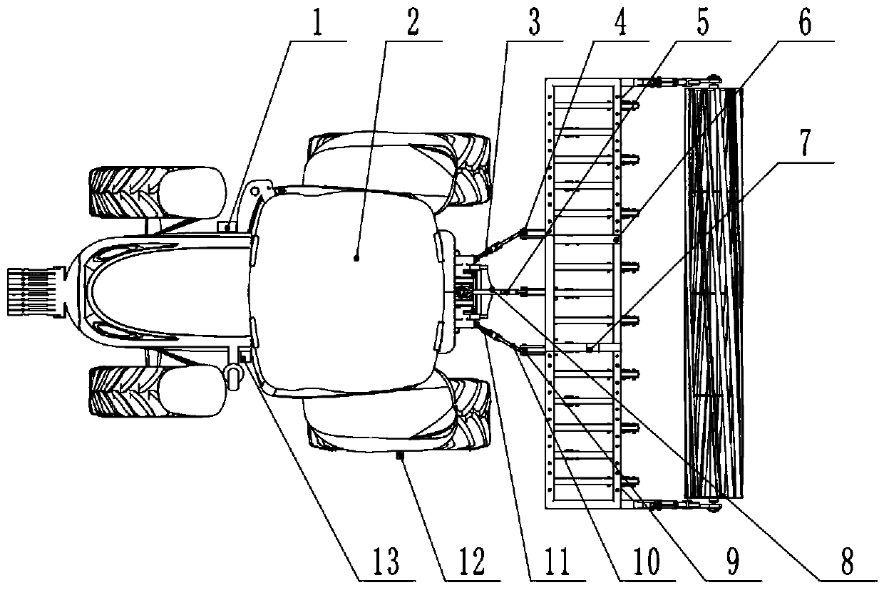
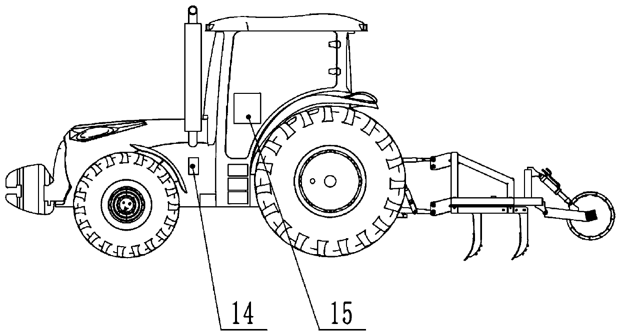
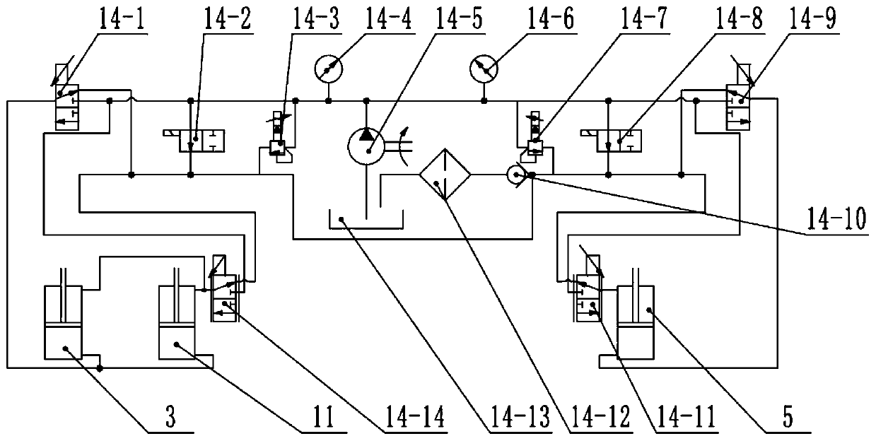
The invention discloses a tractor rear suspension device and a control method thereof. A left lifting oil cylinder of a tractor is connected to a left lower pull rod, the left lower pull rod is connected to a left hanging point of a farm tool through a left force measuring pin shaft in a hanging mode, a right lifting oil cylinder of the tractor is connected to a right lower pull rod, the right lower pull rod is connected to a right hanging point of the farm tool through a right force measuring pin shaft in a hanging mode, and an upper lifting oil cylinder of the tractor is connected to an upper hanging point of the farm tool in a hanging mode; the upper lifting oil cylinder is provided with a first attitude sensor, and the right lower pull rod is provided with a second attitude sensor; a hall sensor and a radar speed measuring instrument are arranged on the tractor; a controller receives and analyzes data sent by the left force measuring pin shaft, the right force measuring pin shaft,the first attitude sensor, the second attitude sensor, the hall sensor and the radar speed measuring instrument; and a hydraulic valve set is used for controlling actions of the left lifting oil cylinder, the right lifting oil cylinder and the upper lifting oil cylinder on the basis of analysis results. According to the tractor rear suspension device, the working condition of the tractor rear suspension device can be analyzed in real time, and the telescopic amount and the pressure of the oil cylinders are optimized and controlled.

Description

technical field [0001] The invention relates to the technical field of agricultural machinery, in particular to a tractor rear suspension device and a control method thereof. Background technique [0002] The agricultural implements are hung on the tractor through the hydraulic suspension device to form a rear suspension unit. The suspension unit changes the force relationship between the tractor and the agricultural implements, and can transfer part of the weight of the agricultural implements, working resistance and front wheel load to the driving wheels of the tractor during work. , so as to increase the vertical load of the drive wheel, improve the adhesion performance of the tractor, facilitate the play of traction force, and improve the productivity of the unit. [0003] According to the adjustment method, the tractor drive wheel loading mechanism can be divided into two types: adjustable rod type and hydraulic type. The rod-adjusting loading mechanism changes the pos...

Claims


Application Information

Patent Timeline
IPC IPC(8): F15B11/16F15B13/06A01B63/102
Inventor 乔晓东孟志军丛岳尚业华付卫强高娜娜
Owner BEIJING RES CENT OF INTELLIGENT EQUIP FOR AGRI
Why Eureka
Try Eureka