Expansion valve

A technology for expansion valves and valve bodies, applied in valve details, safety valves, balance valves, etc., can solve the problems of complex process and high cost, and achieve the effect of reducing the response rate

Pending Publication Date: 2019-06-07
ZHEJIANG SANHUA AUTOMOTIVE COMPONENTS CO LTD
View PDF9 Cites 0 Cited by
  • Summary
  • Abstract
  • Description
  • Claims
  • Application Information

AI Technical Summary

Problems solved by technology

However, it requires special materials to be processed into pressure pads, and the cost is high and the process is relatively complicated

Method used


Image

  • Expansion valve
  • Expansion valve
  • Expansion valve

Examples


Embodiment 1

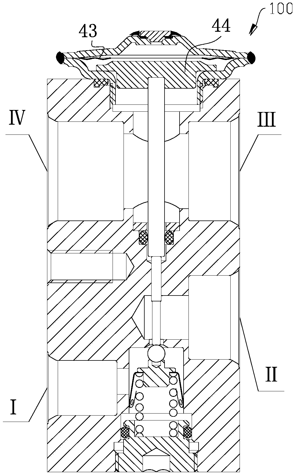
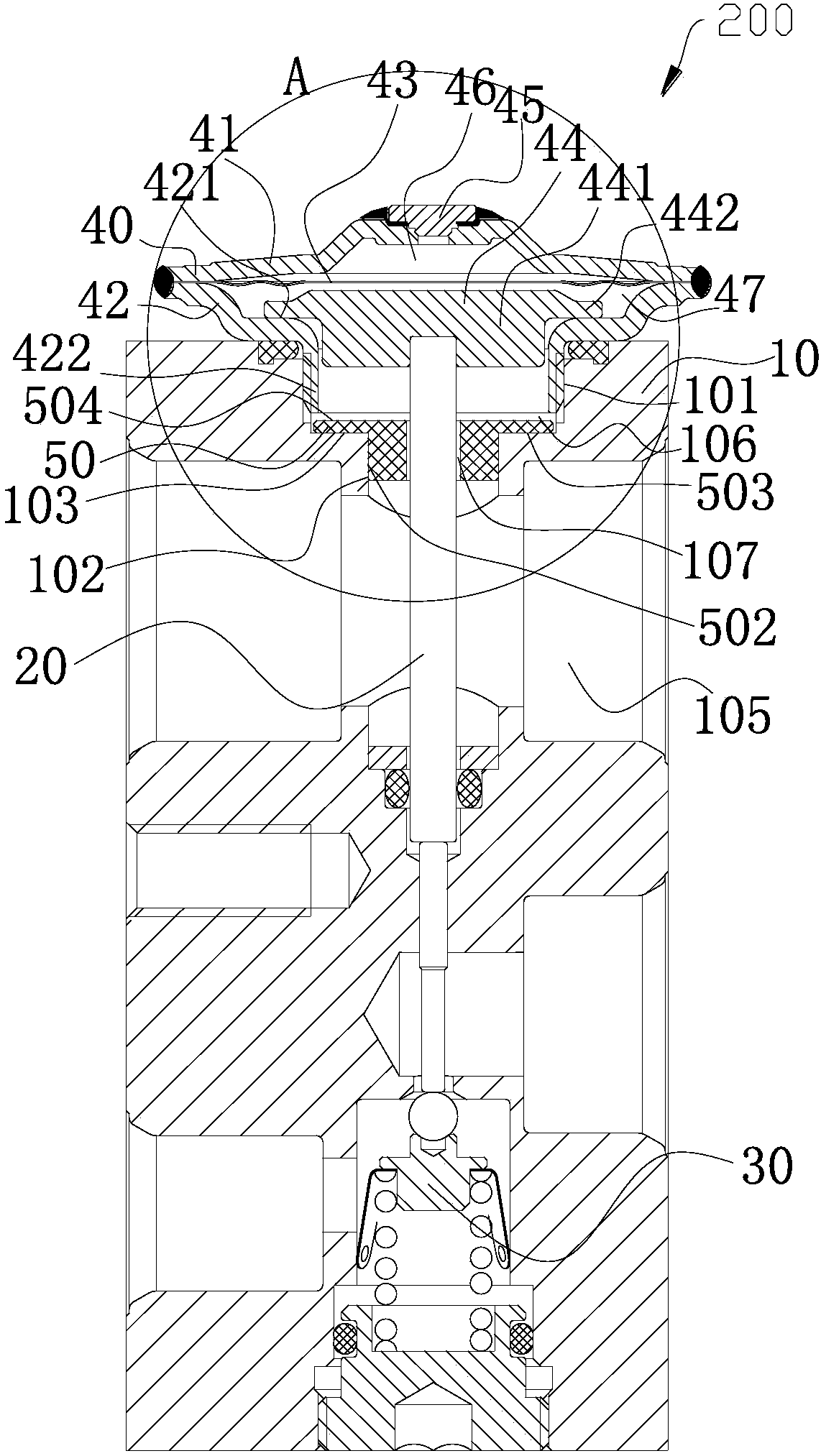
[0023] refer to figure 2 , image 3 and Figure 4 , the expansion valve 200 includes an air box head 40, a valve body 10, a transmission rod 20, and an adjustment seat 30. The air box head 40 is fixed on one side of the valve body 10, the adjustment seat 30 is fixed on the other side of the valve body 10, and the transmission rod 20 is located at Inside the valve body 10 , one end of the transmission rod 20 is fixed or space-limited with the gas tank head 40 , and the other end of the transmission rod 20 is fixed or space-limited with the adjustment seat 30 .

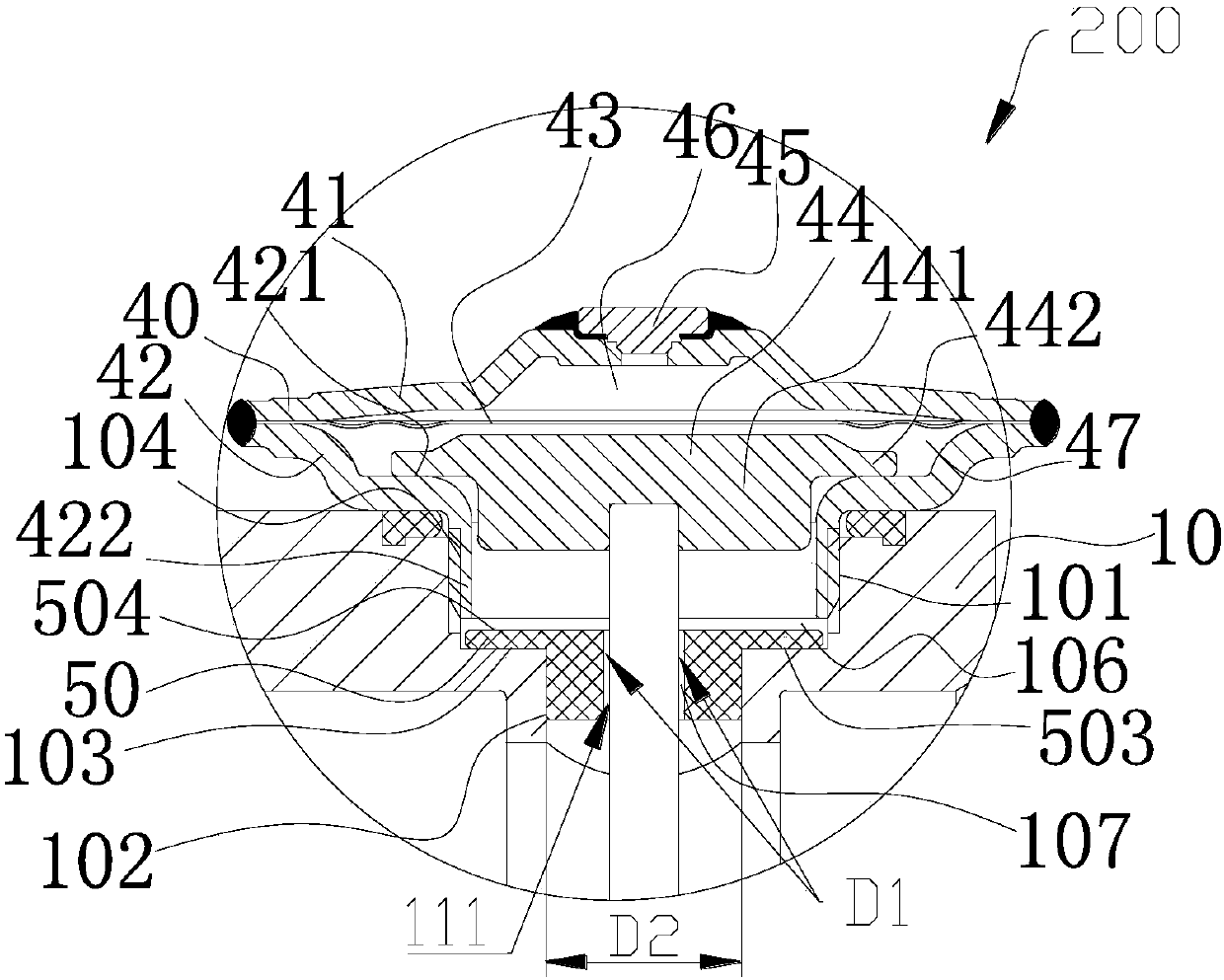
[0024] Air box head 40 comprises air box cover 41, air box seat 42, diaphragm 43, driving plate 44 and sealing plug 45, and diaphragm 43 is positioned between air box cover 41 and air box seat 42, and air box cover 41 and air box The box seat 42 is fixedly arranged, such as by welding. The inside of the gas box head 40 includes a closed chamber 46 and a pressure equalization chamber 47. The diaphragm 43 separates the...

Embodiment 2

[0048] refer to Figure 9 and Figure 10 , Figure 9 A schematic cross-sectional view of the expansion valve 300 is shown. The structure of the expansion valve 300 is roughly the same as that of the expansion valve 200, and its structure can be referred to above.

[0049] The expansion valve 300 includes an isolator 50"', the isolator 50"' includes a through hole 501, the through hole 501 is located at the center of the isolator 50"', and the transmission rod 20 passes through the through hole 501.

[0050] The valve body 10 includes an accommodating cavity 101 , at least part of the air box head 40 is located in the accommodating cavity 101 , and the air box seat 42 and the valve body 10 form a wall portion of the accommodating cavity 101 to be sealed. The valve body 10 includes a second wall portion 102 and a first wall portion 103, the second wall portion 102 and the first wall portion 103 form a stepped shape, wherein the second wall portion 102 generally extends along ...


PUM


Abstract

The invention discloses an expansion valve. The expansion valve comprises a valve body and an air box seat, the expansion valve comprises an isolator, the valve body comprises a first wall part, the first wall part forms a part of an accommodating cavity, and at least part of the isolator is located in the accommodating cavity; and the valve body comprises a fluid cavity located below the accommodating cavity, the isolator comprises a first outer wall part and a second outer wall part, the second outer wall part faces the air box seat, the first outer wall part faces the fluid cavity, the first wall part and the first outer wall part are oppositely arranged, a pressure equalizing cavity and the fluid cavity are mostly partitioned by the first outer wall part and the second outer wall part,the expansion valve comprises a communicating channel, the communicating channel communicates with the pressure equalizing cavity and the fluid cavity, and the equivalent diameter of the communicating channel in the radial extension direction of the valve body is less than the equivalent diameter of the fluid cavity in the radial extension direction of the valve body. The expansion valve is convenient to machine, and the temperature response rate of the valve can be decreased.

Description

technical field [0001] The present invention relates to the field of fluid control. Background technique [0002] refer to figure 1 , figure 1 It is a cross-sectional structure diagram of an expansion valve 100. The refrigerant of the air-conditioning system flows from the port III through the port IV. The pressure and temperature of the refrigerant act on the transmission plate 44 upwards, and act on the diaphragm 43 through the transmission plate 44. [0003] The response speed of the thermal expansion valve is related to the temperature and pressure of the system refrigerant sensed by the gas tank head. Among them, the transmission of refrigerant pressure is realized by acting on the transmission plate, which can be transmitted instantaneously. The temperature transfer is realized through the metal heat conduction of the transmission plate, so in the air conditioning system, the response of the expansion valve has a certain time. [0004] Reference is made to patent d...

Claims


Application Information

Patent Timeline
Patent Type & Authority Applications(China)
IPC IPC(8): F16K31/12F16K17/20F25B41/06F25B41/31
CPCF16K17/20F16K31/12
Inventor 不公告发明人
Owner ZHEJIANG SANHUA AUTOMOTIVE COMPONENTS CO LTD
Why Eureka
Try Eureka