Expansion valve

A technology for expansion valves and valve bodies, applied in valve details, safety valves, balance valves, etc., can solve the problems of complex process and high cost, and achieve the effect of reducing the response rate

Pending Publication Date: 2019-06-07
ZHEJIANG SANHUA AUTOMOTIVE COMPONENTS CO LTD
View PDF9 Cites 0 Cited by
  • Summary
  • Abstract
  • Description
  • Claims
  • Application Information

AI Technical Summary

Problems solved by technology

However, it requires special materials to be processed into pressure pads, and the cost is high and the process is relatively complicated

Method used


Image

  • Expansion valve
  • Expansion valve
  • Expansion valve

Examples


Embodiment 1

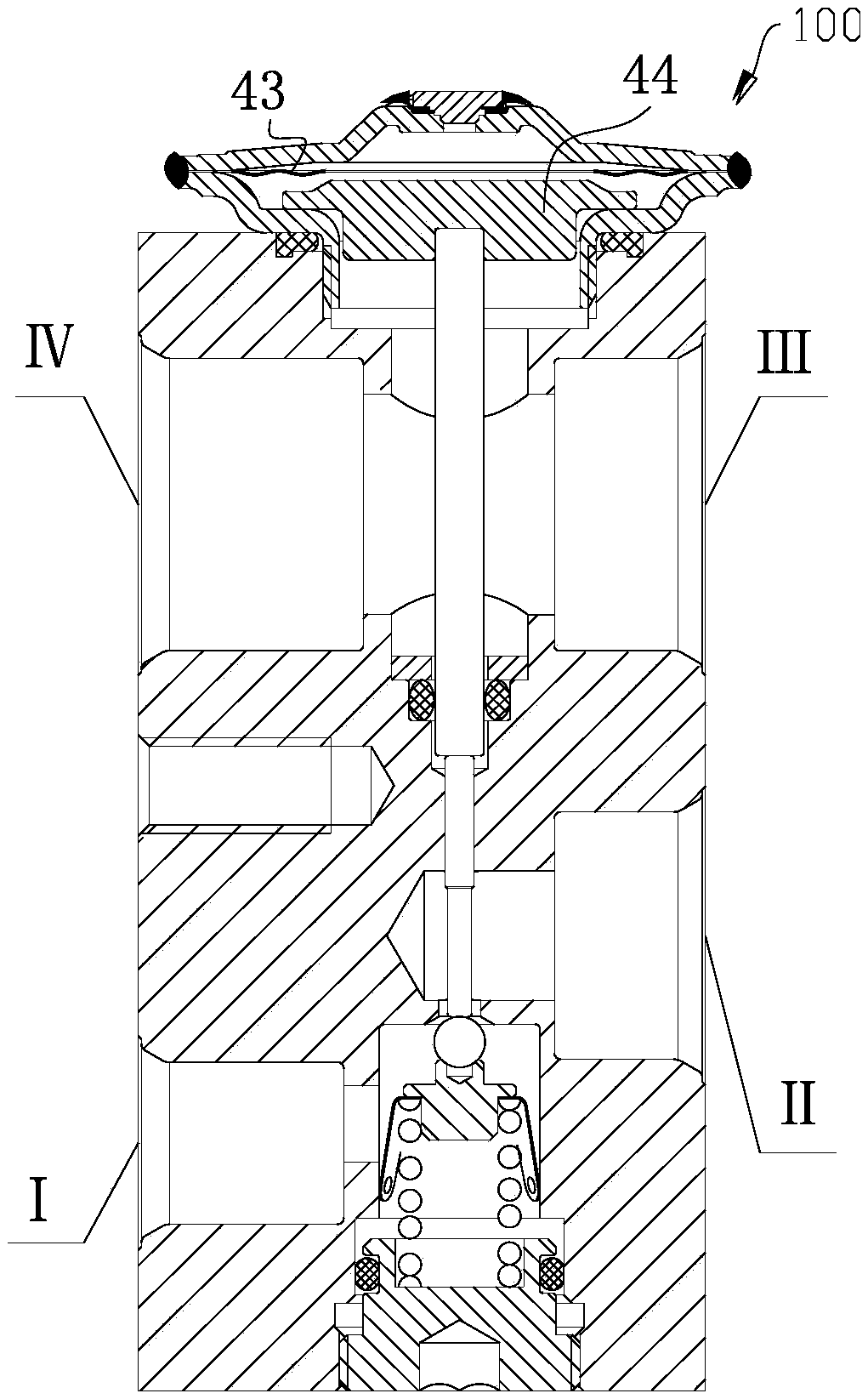
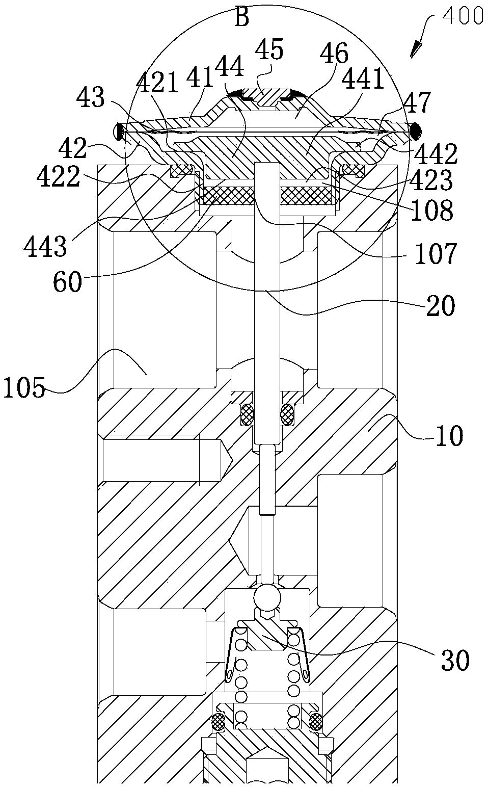
[0022] Reference figure 2 , image 3 with Figure 4 , figure 2 A schematic cross-sectional view of the expansion valve 400 is shown.

[0023] The expansion valve 400 includes an air box head 40, a valve body 10, a transmission rod 20, and an adjusting seat 30. The air box head 40 is fixed on one side of the valve body 10, the adjusting seat 30 is fixed on the other side of the valve body 10, and the transmission rod 20 is located in the valve body. Inside the body 10, one end of the transmission rod 20 is fixed or restricted with the air box head 40, and the other end of the transmission rod 20 is fixed or restricted with the adjusting seat 30.

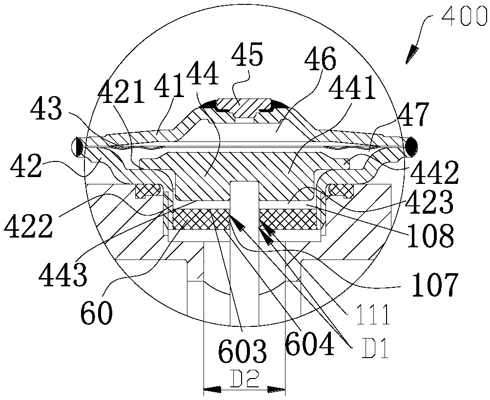
[0024] The air box head 40 includes an air box cover 41, an air box seat 42, a diaphragm 43, a transmission piece 44 and a sealing plug 45. The diaphragm 43 is located between the air box cover 41 and the air box seat 42, and the air box cover 41 and the air box The box base 42 is fixedly arranged, for example, by welding. The inside of ...

Embodiment 4

[0052] Reference Picture 11 , Picture 11 The schematic cross-sectional structure of the expansion valve 500 is shown. The general structure of the expansion valve 500 is the same as that of the expansion valve 400. The expansion valve 500 includes a spacer 60. The air box seat 42 includes a convex wall portion 424, which is located at the first inner wall portion 422. The convex wall portion 424 extends inwardly from the first inner wall portion 422, and at least part of the third outer wall portion 604 abuts the convex wall portion 109.

[0053] Should understand, Figure 5-Figure 10 The structure of the spacer shown can be applied to the structure of the expansion valve 500.

[0054] Reference Figure 5 with Image 6 The spacer 60' includes a through hole 606, the through hole 606 is located at a peripheral position of the through hole 601, and at least a part of the through hole 606 does not fall into the convex wall portion 424 area.

[0055] Reference Figure 7 with Picture 8...


PUM


Abstract

The invention discloses an expansion valve. The expansion valve comprises a valve body and an air box seat, the expansion valve comprises an isolator, the valve body comprises a first wall part, the first wall part forms a part of an accommodating cavity, and at least part of the isolator is located in the accommodating cavity; and the valve body comprises a fluid cavity, the isolator comprises afirst outer wall part and a second outer wall part, the second outer wall part faces the air box seat, the first outer wall part faces the fluid cavity, a pressure equalizing cavity and the fluid cavity are mostly partitioned by the first outer wall part and the second outer wall part, the expansion valve comprises a communicating channel, the communicating channel communicates with the pressure equalizing cavity and the fluid cavity, and the equivalent diameter of the communicating channel in the radial extension direction of the valve body is less than the equivalent diameter of the fluid cavity in the radial extension direction of the valve body. The expansion valve is convenient to machine, and the temperature response rate of the valve can be decreased.

Description

Technical field [0001] The invention relates to the technical field of fluid control. Background technique [0002] Reference figure 1 , figure 1 It is a cross-sectional structure diagram of an expansion valve 100. The air conditioning system refrigerant flows from the port III through the port IV, and the pressure and temperature of the refrigerant act upward on the transmission plate 44, and act on the diaphragm 43 through the transmission plate 44. [0003] The response speed of the thermal expansion valve is related to the temperature and pressure of the system refrigerant sensed by the air box head. Among them, the transmission of the pressure of the refrigerant is realized by acting on the transmission plate, which can be transmitted instantaneously. The temperature transmission is realized through the metal heat conduction of the transmission piece, so in the air conditioning system, the response of the expansion valve has a certain time. When this kind of time response fr...

Claims


Application Information

Patent Timeline
Patent Type & Authority Applications(China)
IPC IPC(8): F16K31/12F16K17/20F25B41/06F25B41/31
CPCF16K17/20F16K31/12
Inventor 不公告发明人
Owner ZHEJIANG SANHUA AUTOMOTIVE COMPONENTS CO LTD
Why Eureka
Try Eureka