
Display module and display equipment

A display module and display panel technology, which is applied in nonlinear optics, instruments, optics, etc., can solve the problems of being unable to achieve narrower black border aesthetics, destroying the integrated aesthetics of edges, and being difficult to use as the appearance of display devices, etc. , to achieve the effect of good appearance consistency, improved production efficiency, and simple appearance treatment process

Inactive Publication Date: 2019-06-07
江门创维显示科技有限公司
View PDF11 Cites 9 Cited by
  • Summary
  • Abstract
  • Description
  • Claims
  • Application Information

AI Technical Summary

Problems solved by technology

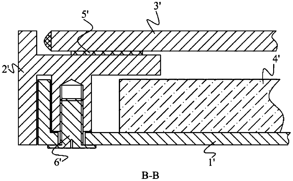
Because the backplane 1' is generally formed by stamping galvanized steel, aluminum plate or milling aluminum-plastic plate, the forming process limits the structure of the backplane 1', making it difficult for the backplane 1' to be used as the front and side appearance of the display device
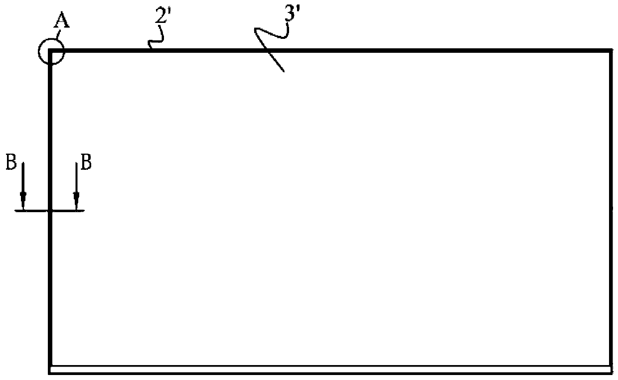
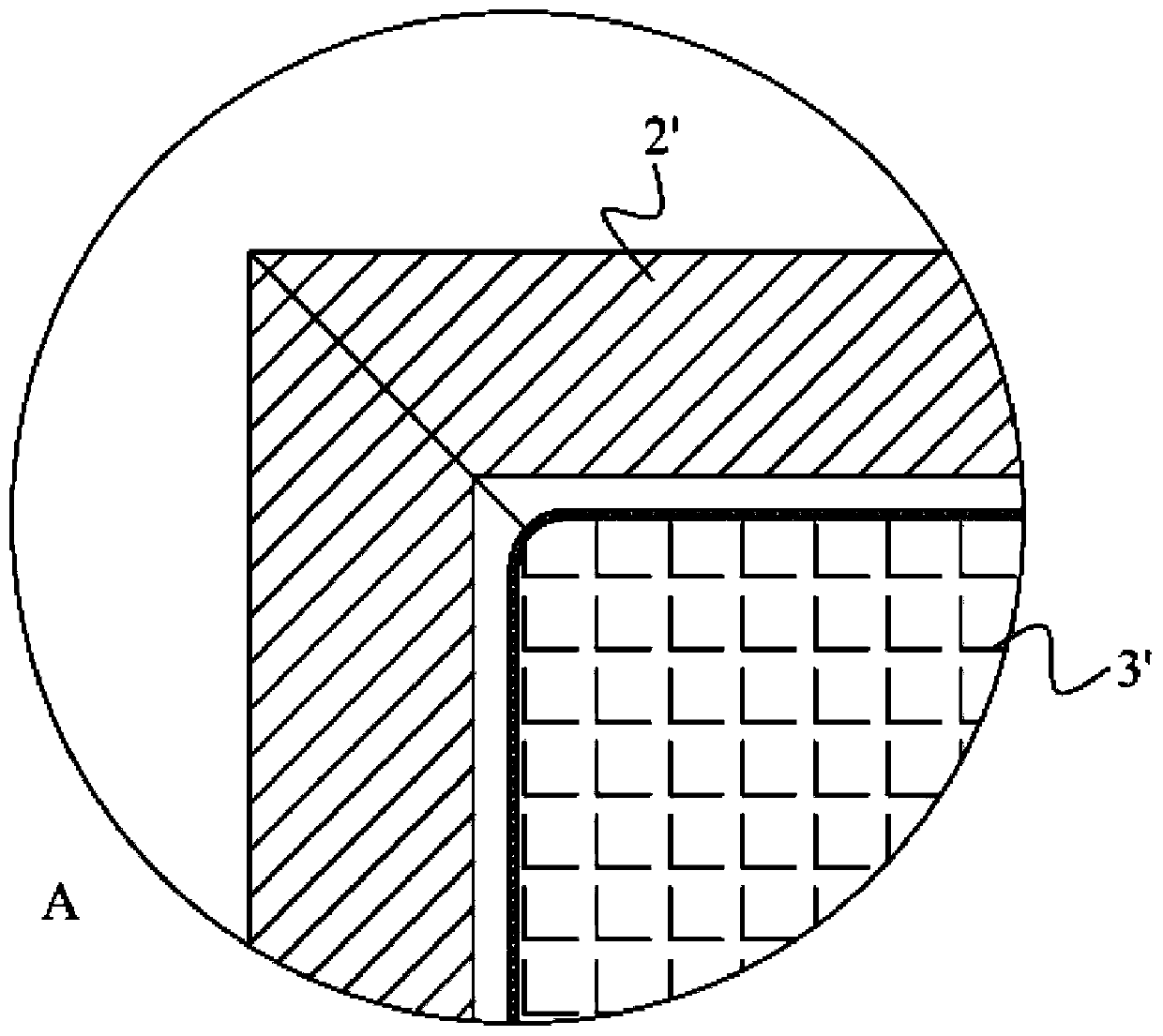
[0004] In the existing technology, in order to meet the appearance requirements of the display device and to meet the conventional stacking assembly process, the middle frame 2' is selected as the package of the four sides of the backplane 1', and the middle frame 2' and the backplane 1' are connected by screws. 6' is fixed, and the middle frame 2' becomes the appearance of the front and side of the back panel 1'; the LCD panel 3' is fixed on the middle frame 2' by double-sided foam glue 5'; in addition, too many structures require more sides The space requires wider black borders on the side of the LCD panel 3', but this not only destroys the aesthetics of the edge integration, but also fails to achieve the aesthetics of narrower black borders, and also needs to be treated for the appearance of the middle frame 2' cost pay

Method used


Image

  • Display module and display equipment
  • Display module and display equipment
  • Display module and display equipment

Examples


Embodiment Construction

[0037] In order to make the technical problems solved by the present invention, the technical solutions adopted and the technical effects achieved clearer, the technical solutions of the present invention will be further described below in conjunction with the accompanying drawings and through specific implementation methods.

[0038] This embodiment provides a display device, and the display device may be an electronic device with an image display function such as a television, a monitor, and an advertising machine. In this embodiment, the display device is introduced by taking a television as an example.

[0039] Such as Figure 4 As shown, the TV includes a display module, and the display module includes a backlight module and a display panel 3 . The display panel 3 is arranged on the front side of the backlight module, and the backlight module provides a uniform surface light source for the display panel 3 so as to display images on the display panel 3 .

[0040] Such as...


PUM


Abstract

The invention discloses a display module and display equipment, and relates to the technical field of the display equipment. The display module comprises a back plate and a middle frame; the edges ofthe three sides of the back plate are bent towards the front side to form first flanging, the end of the first flanging is bent towards the inner side to form an abutting part, and the edge of the remaining side of the back plate is bent towards the rear side to form second flanging; the middle frame comprises a U-shaped frame and a lower side frame, the U-shaped frame is arranged on the inner side of the first flanging, the abutting part abuts against the front side face of the U-shaped frame, and the inner side of the U-shaped frame is provided with a clamping groove for containing the edgeof an optical element; and the lower side frame is connected with the second flanging and shields an opening of the U-shaped frame. According to the display module, defects such as knife edges at theend of the back plate are hidden through the first flanging, the abutting part and the second flanging, the middle frame does not need to be used as an appearance piece at the edge of the display module, thus appearance faces of the display module are all provided by the back plate, and the appearance consistency is better; and when the back plate serves as the appearance piece, an appearance treatment process is simple, the cost is advantageously lowered, and the production efficiency is improved.

Description

technical field [0001] The present invention relates to the technical field of display devices, in particular to a display module and a display device. Background technique [0002] Compared with LCD TVs (Liquid Crystal Display, LCD), Organic Light-Emitting Diode TVs (Organic Light-Emitting Diode, OLED) have certain advantages in terms of borderless, ultra-thin, and image quality, but their prices remain high. , and rapidly developed a frameless, ultra-thin LCD low-cost module. [0003] The LCD TV has a backlight module, and the backlight module and the liquid crystal panel are fixed by pasting, thereby realizing a frameless structure. As a whole, the backlight module requires a stable structure before assembling the liquid crystal panel. Such as Figure 1-Figure 3 As shown, the real working parts of the backlight module are the light source (not shown in the figure) and the optical element 4'. In the group are the light guide plate) and film materials (reflector, diffuse...

Claims


Application Information

Patent Timeline
Patent Type & Authority Applications(China)
IPC IPC(8): G02F1/1333
Inventor 杨宝磊朱莹
Owner 江门创维显示科技有限公司
Learn More