Supercharge Your Innovation With Domain-Expert AI Agents!

Eyeball tracking device and method

An eye tracking and eye technology, applied in the input/output of user/computer interaction, computer components, graphic reading, etc., can solve the problem of inaccurate gaze information, inability to reflect the real characteristics of the eye, and incomplete eye pupil information And other issues

Pending Publication Date: 2019-06-07
BEIJING 7INVENSUN TECH
View PDF7 Cites 7 Cited by
  • Summary
  • Abstract
  • Description
  • Claims
  • Application Information

AI Technical Summary

Problems solved by technology

In the pen-and-hold structure eye tracking device, the image acquisition device is set in front of the eye, and the image acquisition device forms a certain angle with the horizontal line where the eye is located, so the image it collects is not the image directly facing the eye. The eye image may be distorted and may not reflect the true characteristics of the eye, which may result in inaccurate fixation information determined from the eye image
In addition, for users who wear glasses, the eyeball in the eye image captured by the pen-hold structure is easily blocked by the glasses, which may cause incomplete eye pupil information collected by the image acquisition device

Method used


Image

  • Eyeball tracking device and method
  • Eyeball tracking device and method
  • Eyeball tracking device and method

Examples


Embodiment 1

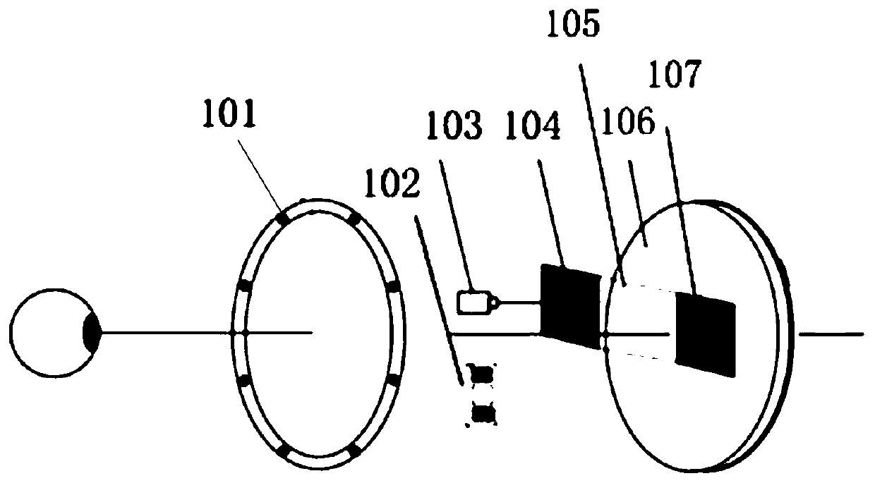
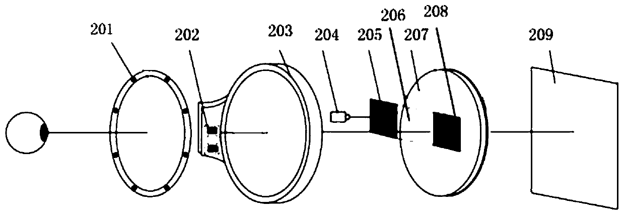
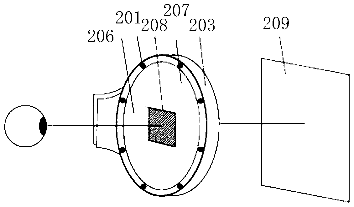
[0051] The schematic diagrams of the eye tracking device provided in Embodiment 1 or Embodiment 2 are for a single eye, and may also be an eye tracking device for both eyes during a specific implementation. The eye tracking device for both eyes can simply replicate all the modules in the device provided in Embodiment 1 or Embodiment 2, that is, the left and right eyes each have all the modules in the eye tracking device provided in Embodiment 1 or Embodiment 2. It is also possible to have part of the modules in the eye tracking device provided in Embodiment 1 or Embodiment 2 for each of the left and right eyes, and the two share another part of the modules in the eye tracking device. In the specific implementation process of the eye tracking device for both eyes, there is no limitation on whether the specific modules in the device are separated or multiplexed, and it should not be understood as departing from the spirit and scope of the technical solutions of the embodiments of...

Embodiment 3

[0054] Embodiment 3 provides an optical path diagram, and based on the optical path diagram and the eye tracking device provided in Embodiment 1, Embodiment 4 provides an eye tracking method. like Figure 5 As shown, the method of eye tracking may include:

[0055] 401. The light source emits light to the eyes.

[0056] The light source emits light to the eyes. Since the infrared light will not affect the vision of the eyes, the light source can be an infrared light source and there can be one or more infrared light sources. When there are multiple infrared light sources, the multiple infrared light sources can be preset The arrangement can be in the shape of a character, a line, etc. There is no limitation on the arrangement of multiple infrared light sources here. In order not to block the sight of the eyes, the light source can be arranged on the edge or outside of the visual range of the eyes.

[0057] Before the light source emits light to the eyes, it may also include...

Embodiment 4

[0067] Embodiment 4 provides an eye tracking method. In Embodiment 4, the waveguide unit sends the parallel light to the image acquisition unit, which may include a waveguide output module receiving the parallel light and transmitting the parallel light to the waveguide. The light is transmitted to the waveguide output module, and then the waveguide output module projects the parallel light to the image acquisition unit. Based on the eye tracking device provided in Embodiment 2 and the optical path diagram provided in Embodiment 3, Embodiment 5 provides another implementation of an eye tracking method. Please refer to Image 6 , Embodiment five may include:

[0068] 501. The light source emits light to the eyes.


PUM


Abstract

The embodiment of the invention provides an eyeball tracking device and method. The eyeball tracking device can comprise a collimation unit, a waveguide unit, an image acquisition unit and a main control unit. The method can comprise the steps that the collimation unit adjusts reflected light of the eyes into parallel light and transmits the parallel light to the waveguide unit; the waveguide unitprojects the parallel light adjusted by the collimation unit to the image acquisition unit; the image acquisition unit acquires an eye image according to the parallel light and transmits the eye image to the main control unit; the main control unit determines gaze information according to the eye image. In the eyeball tracking device, the image acquisition unit can ensure that the acquired imageof the eye is the image directly facing the eye according to the parallel light, and the accuracy degree of fixation information determined according to the image directly facing the eye is high.

Description

technical field [0001] The present invention relates to the field of eye tracking, in particular to an eye tracking device and method. Background technique [0002] Among the existing eye tracking devices based on the optical recording method, eye tracking devices with a pen-hold structure are relatively common. In the pen-and-hold structure eye tracking device, the image acquisition device is set in front of the eye, and the image acquisition device forms a certain angle with the horizontal line where the eye is located, so the image it collects is not the image directly facing the eye. The eye image may be distorted and may not reflect the true characteristics of the eye, which may result in inaccurate gaze information determined from the eye image. In addition, for users who wear glasses, the eyeball in the eye image captured by the pen-hold structure is easily blocked by the glasses, which may cause incomplete eye pupil information collected by the image acquisition dev...

Claims


Application Information

Patent Timeline
IPC IPC(8): G06F3/01
Inventor 王文斌王云飞黄通兵
Owner BEIJING 7INVENSUN TECH
Features
  • R&D
  • Intellectual Property
  • Life Sciences
  • Materials
  • Tech Scout
  • Unparalleled Data Quality
  • Higher Quality Content
  • 60% Fewer Hallucinations
Learn More