
Automatic cooling device for transformer

An automatic cooling device and transformer technology, applied in the direction of transformer/inductor cooling, etc., can solve the problems of transformer cooling without automation and intelligence, poor cooling effect and cooling efficiency, and inconvenient power access from the power grid, and achieve cooling effect. Good, good use efficiency, ensure the effect of heat dissipation

Inactive Publication Date: 2019-06-07
中科电力装备集团变压器有限公司
View PDF0 Cites 6 Cited by
  • Summary
  • Abstract
  • Description
  • Claims
  • Application Information

AI Technical Summary

Problems solved by technology

At present, most large-scale transformers use oil circulation to dissipate heat, and small transformers use heat sinks or heat sinks and fans to dissipate heat. The heat dissipation is not automatic and intelligent, the heat dissipation effect and heat dissipation efficiency are not good, and the equipment is in the heat dissipation state for a long time, which consumes a lot of power

Method used


Image

  • Automatic cooling device for transformer
  • Automatic cooling device for transformer

Examples


Embodiment Construction

[0023] In order to make the object, technical solution and advantages of the present invention clearer, the present invention will be further described in detail below in conjunction with specific embodiments and with reference to the accompanying drawings. It should be understood that these descriptions are exemplary only, and are not intended to limit the scope of the present invention. Also, in the following description, descriptions of well-known structures and techniques are omitted to avoid unnecessarily obscuring the concept of the present invention.

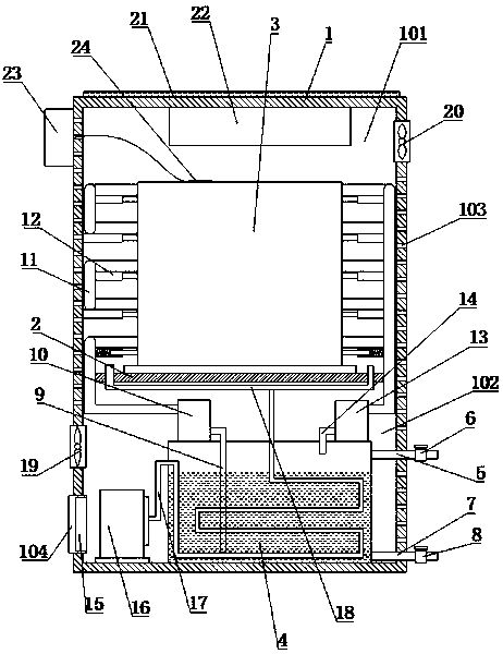
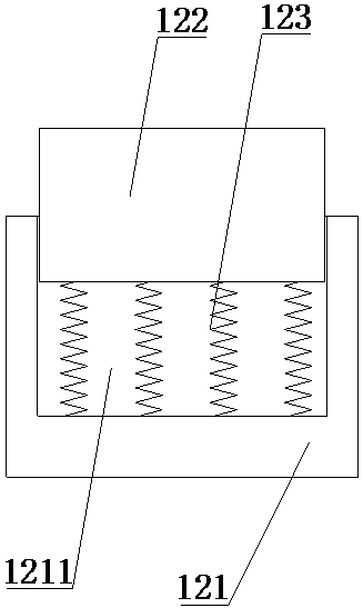
[0024] Such as Figure 1-2 As shown, a transformer automatic cooling device proposed by the present invention includes a device housing 1, a partition plate 2, a transformer 3, a circulating water tank 4, a water inlet pipe 5, a water inlet control valve 6, a drain pipe 7, a drainage control valve 8, Water suction pipe 9, water pump 10, water cooling pipe 11, heat conduction device 12, condenser 13, water outlet pipe 14,...


PUM


Abstract

The invention discloses an automatic cooling device for a transformer. A partition plate is horizontally arranged in a device shell body, and the device shell body is divided into a transformer installing bin on the upper part and a cooling bin on the lower part; an air inlet and a plurality of heat dissipation holes are formed in the device shell body; the air inlet is formed in the lower part ofthe partition plate; the transformer is arranged on the partition plate and is located in the transformer installing bin; a recycling water box is arranged in the cooling bin; one end of a water inlet pipe is connected with an exterior water source, and the other end of the water inlet pipe extends into the device shell body and is connected with the upper part of the recycling water box; a waterinlet control valve is arranged on the pipeline, on the outer side of the device shell body, of the water inlet pipe; one end of a water discharging pipe is connected with the lower part of the recycling water box, and the other end of the water discharging pipe extends out of the device shell body and is connected with a water discharging system; and a water discharging control valve is arrangedon the pipeline, on the outer side of the device shell body, of the water discharging pipe. According to the automatic cooling device for the transformer, cooling and heat dissipation can be automatically conducted according to the temperature of the transformer, the cooling efficiency is high, the temperature cooling effect is great, heat dissipation is ensured and at the same time energy is saved due to intelligent heat dissipation and recycling of cooling water, and the application range is wider.

Description

technical field [0001] The invention relates to the technical field of transformer cooling devices, in particular to an automatic cooling device for transformers. Background technique [0002] Transformer is a device that uses the principle of electromagnetic induction to change AC voltage. The main components are primary coil, secondary coil and iron core (magnetic core). The main functions are: voltage conversion, current conversion, impedance conversion, isolation, voltage stabilization (magnetic saturation transformer), etc. [0003] In electrical equipment and wireless circuits, transformers are often used for step-down voltage, matching impedance, safety isolation, etc. In a generator, whether the coil moves through the magnetic field or the magnetic field moves through the fixed coil, an electric potential can be induced in the coil. In both cases, the value of the magnetic flux remains the same, but the amount of magnetic flux intersecting the coil is different. Ch...

Claims


Application Information

Patent Timeline
IPC IPC(8): H01F27/16H01F27/08
Inventor 王小飞杨坤生施洪华王丹
Owner 中科电力装备集团变压器有限公司
Learn More