Broadband patch antenna based on differential resonator feed

A patch antenna and resonator technology, which is applied in the field of communication, can solve the problems of complex transceiver antennas and increased cost of communication systems, and achieve the effects of low price, simple structure and low profile.

Active Publication Date: 2019-06-07
深圳市卓睿通信技术有限公司
View PDF10 Cites 4 Cited by
  • Summary
  • Abstract
  • Description
  • Claims
  • Application Information

AI Technical Summary

Problems solved by technology

If corresponding antenna units and arrays are developed for these frequency bands, the transmitting and receiving antennas of the communication system will become very complicated and the cost will be significantly increased

Method used


Image

  • Broadband patch antenna based on differential resonator feed
  • Broadband patch antenna based on differential resonator feed
  • Broadband patch antenna based on differential resonator feed

Examples


Embodiment

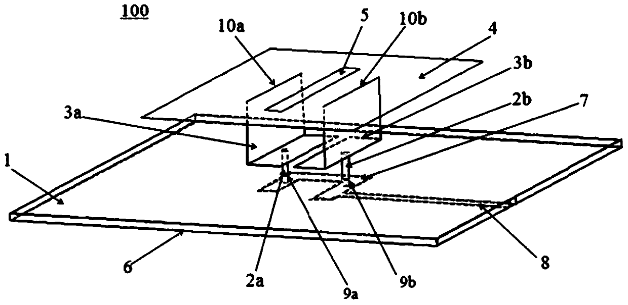
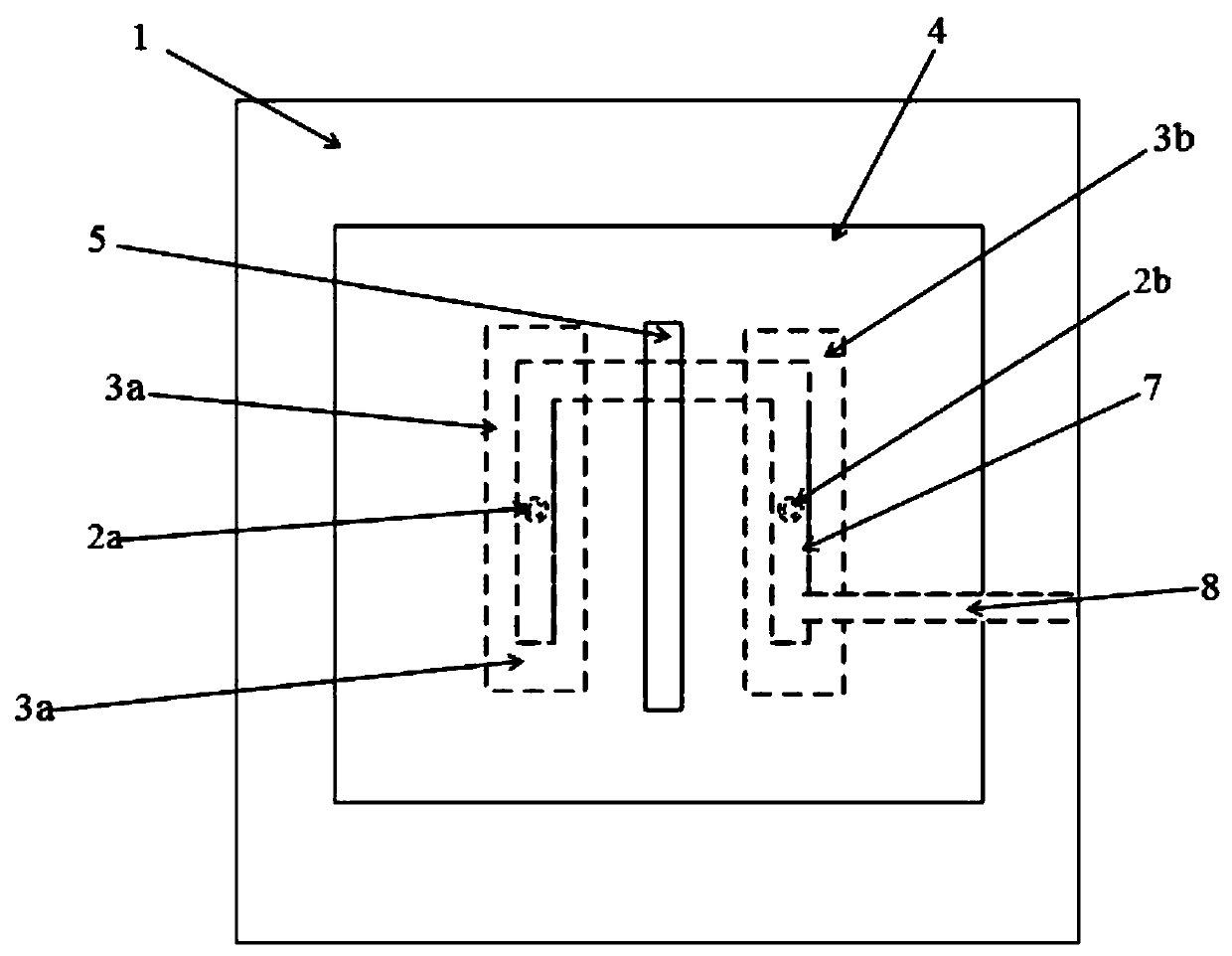
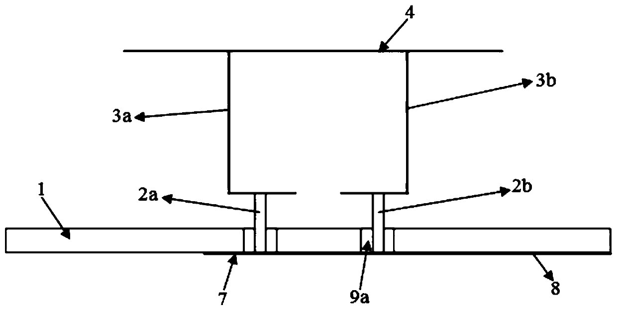
[0028] Please refer to Figure 1-Figure 3 , the present embodiment is a broadband patch antenna 100 based on differential resonator feeding, which includes a metal base plate 1, a first L-shaped folded piece 3a and a second L-shaped folded piece 3b located above the metal base plate 1, arranged on The top of the first L-shaped folded piece 3a and the second L-shaped folded piece 3b and the radiation patch 4 arranged parallel to the metal bottom plate 1, the dielectric substrate 6 arranged on the lower surface of the metal bottom plate 1, and formed on the dielectric substrate 6 The resonant unit 7 and the feeder 8 connected to the resonant unit 7, one of the horizontal folding surfaces of the first L-shaped folded sheet 3a and the second L-shaped folded sheet 3b pass through the first metal probe 2a and the second metal probe respectively. The needle 2b vertically passes through the metal bottom plate 1 and the dielectric substrate 6 to connect with the resonant unit 7 .

[0...


PUM


Abstract

The invention discloses a broadband patch antenna based on differential resonator feed. The antenna comprises a metal bottom plate, an L-shaped folding sheet located above the metal bottom plate, a radiation patch which is arranged at the top of the L-shaped folding sheet and is parallel to the metal bottom plate, a dielectric substrate which is arranged on the lower surface of the metal bottom plate in an attached mode, a resonance unit which is formed on the dielectric substrate, and a the feeder line connected with the resonance unit. One horizontal folding face of the L-shaped folding sheet perpendicularly passes through the metal bottom plate and the dielectric substrate to be connected with the resonance unit through a metal probe. According to the invention, the antenna reduces thecross polarization by using differential feed, and works in four resonant modes. The bandwidth reaches 63.7%, and the profile height of the antenna is only 0.158 vacuum wavelengths; and a flat gain and a stable radiation pattern are kept right above the antenna in the pass band.

Description

【Technical field】 [0001] The invention belongs to the technical field of communication, in particular to a broadband patch antenna based on differential resonator feeding. 【Background technique】 [0002] In recent years, with the rapid development of wireless communication and increasingly complex application scenarios, the bandwidth and other performance requirements of antennas in wireless communication systems are getting higher and higher. Microstrip patch antennas are widely used in various wireless communications due to their advantages of low profile, light weight, easy processing and low cost. [0003] However, one disadvantage of microstrip patch antennas is that they have a relatively narrow bandwidth, making them difficult to apply in broadband communications. Many broadband techniques have been studied over the years in an attempt to increase the bandwidth of microstrip antennas. In the existing technical solutions, some add parasitic patches in the horizontal ...

Claims


Application Information

Patent Timeline
Patent Type & Authority Applications(China)
IPC IPC(8): H01Q1/22H01Q1/36H01Q1/38H01Q1/50
Inventor 袁涛洪凯东张晓朱玉建黄冠龙韩崇志
Owner 深圳市卓睿通信技术有限公司
Why Eureka
Try Eureka