Eureka AIR delivers breakthrough ideas for toughest innovation challenges, trusted by R&D personnel around the world.

Multimode horn antenna

a horn antenna and multi-mode technology, applied in the direction of antennas, waveguide horns, electrical equipment, etc., can solve the problems of limited bandwidth, high dissipation or reflection losses, low power capabilities, etc., and achieve low cross polarisation, low side lobes, and high electrical efficiency.

Inactive Publication Date: 2002-12-19
ALCATEL LUCENT SAS
View PDF2 Cites 8 Cited by
  • Summary
  • Abstract
  • Description
  • Claims
  • Application Information

AI Technical Summary

Benefits of technology

[0001] The present invention relates to multimode feed horn antennas, widely used for communication purposes. More particularly, but not exclusively, this invention relates to a multimode feed horn antenna for use in a multiple mode horn antenna system to provide beam radiation patterns that have substantially equal E-plane and H-plane beamwidths over the operating frequency band of a signal, low cross polarisation, low side lobes and high electrical efficiency.

Problems solved by technology

All of these approaches, however, have had certain drawbacks, such as limitation to narrow bandwidths, high dissipation or reflection losses, low power capabilities, limitation to particular polarisation, cost of fabrication, or complexity.

Method used


Image

  • Multimode horn antenna
  • Multimode horn antenna
  • Multimode horn antenna

Examples


Embodiment Construction

[0017] The usable bandwidth related to the content of the propagation modes of a signal, and determined by the phase orientation of the modes in that bandwidth. These propagation modes include the transverse electric TE modes where the electric field lines are in the transverse plane of wave propagation, and the transverse magnetic TM modes where the magnetic field lines are in the transverse plane of wave propagation. The orientation of the electric and magnetic fields in the various TE and TM modes defines the mode content of the signal.

[0018] An antenna has transmission capabilities for transmitting a signal having a frequency consistent with a communications network, such as the Ka frequency bandwidth, but can be used for any applicable frequency bandwidth, both commercial and military, including the Ka-band.

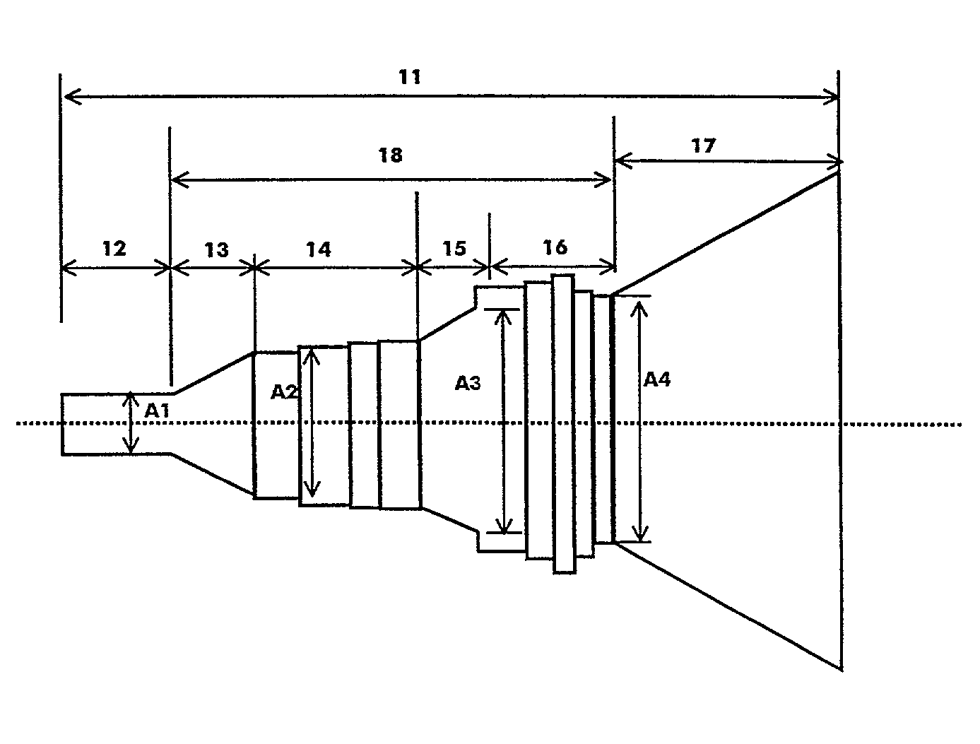
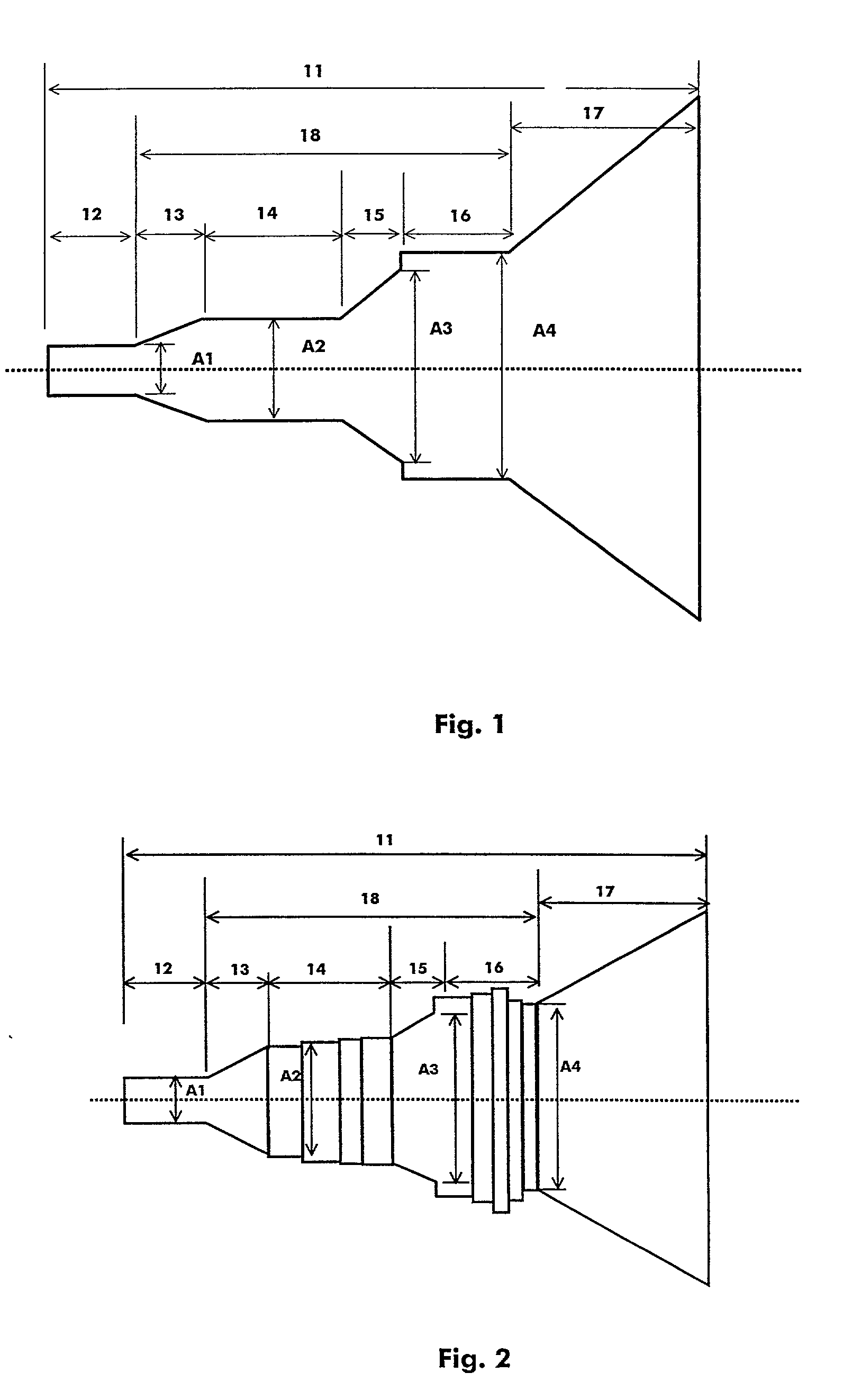
[0019] Referring to FIG. 1, a multimode horn antenna 11 embodying the present invention is shown. The horn antenna 11 forms a part of an antenna system, which includes signa...


PUM


Abstract

The horn (11) comprises a plurality of transition steps can also be provided to increase the control of amplitude and phase content of the TE11 and TM11 modes at the output of the corn horn mouth (17) and suppress the unwanted TE12 mode. This control of the mode content provides for minimizing the length of the multimode horn antenna for a desired aperture size at the desired operational bandwidth, and provide low sidelobes and low cross-polarization, over a relatively wide bandwidth, with high electrical efficiency.

Description

OBJECT OF THE INVENTION[0001] The present invention relates to multimode feed horn antennas, widely used for communication purposes. More particularly, but not exclusively, this invention relates to a multimode feed horn antenna for use in a multiple mode horn antenna system to provide beam radiation patterns that have substantially equal E-plane and H-plane beamwidths over the operating frequency band of a signal, low cross polarisation, low side lobes and high electrical efficiency.STATE OF THE ART[0002] It is known the use of conical feed horns for radiating electromagnetic energy from a waveguide into free space, to produce beams having low sidelobes and equal E- and H-plane beamwidths.[0003] A number of proposals have been made for producing these desirable characteristics in a horn. All of these approaches, however, have had certain drawbacks, such as limitation to narrow bandwidths, high dissipation or reflection losses, low power capabilities, limitation to particular polari...

Claims


Application Information

Patent Timeline
Patent Type & Authority Applications(United States)
IPC IPC(8): H01P1/16H01Q13/02
CPCH01P1/16H01Q13/025H01Q13/0208
Inventor JUDASZ, THIERRY
Owner ALCATEL LUCENT SAS
Why Eureka
Eureka Blog
Learn More