High-gain differential dual-polarized dielectric patch antenna based on high-order mode

A patch antenna, high-gain technology, used in antennas, resonant antennas, electrical short antennas, etc., can solve the problem of rare dielectric patch antennas, achieve high gain, expand bandwidth, and reduce input impedance.

Active Publication Date: 2020-01-10
江苏迅海智能科技有限公司
View PDF3 Cites 9 Cited by
  • Summary
  • Abstract
  • Description
  • Claims
  • Application Information

AI Technical Summary

Problems solved by technology

Therefore, dielectric patch antennas have great application potential, but so far, designs based on dielectric patch antennas are still very rare

Method used


Image

  • High-gain differential dual-polarized dielectric patch antenna based on high-order mode
  • High-gain differential dual-polarized dielectric patch antenna based on high-order mode
  • High-gain differential dual-polarized dielectric patch antenna based on high-order mode

Examples


Embodiment Construction

[0019] The present invention will be further described below in conjunction with the accompanying drawings and specific embodiments.

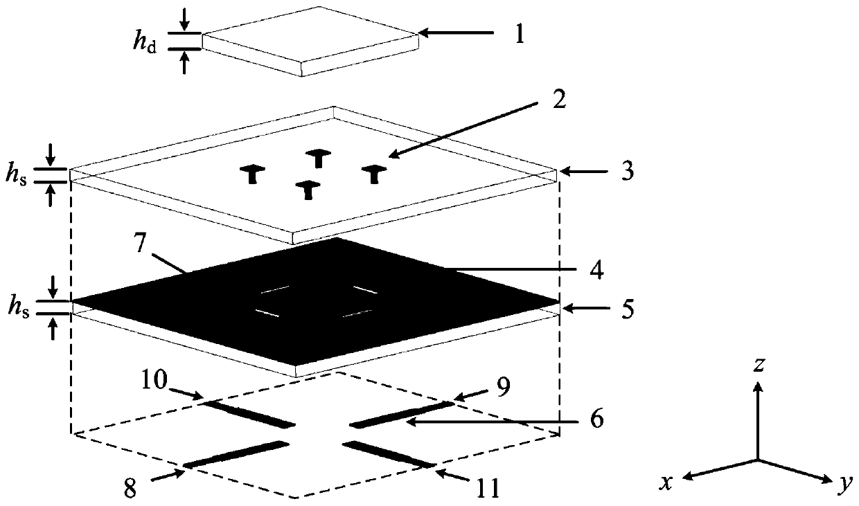
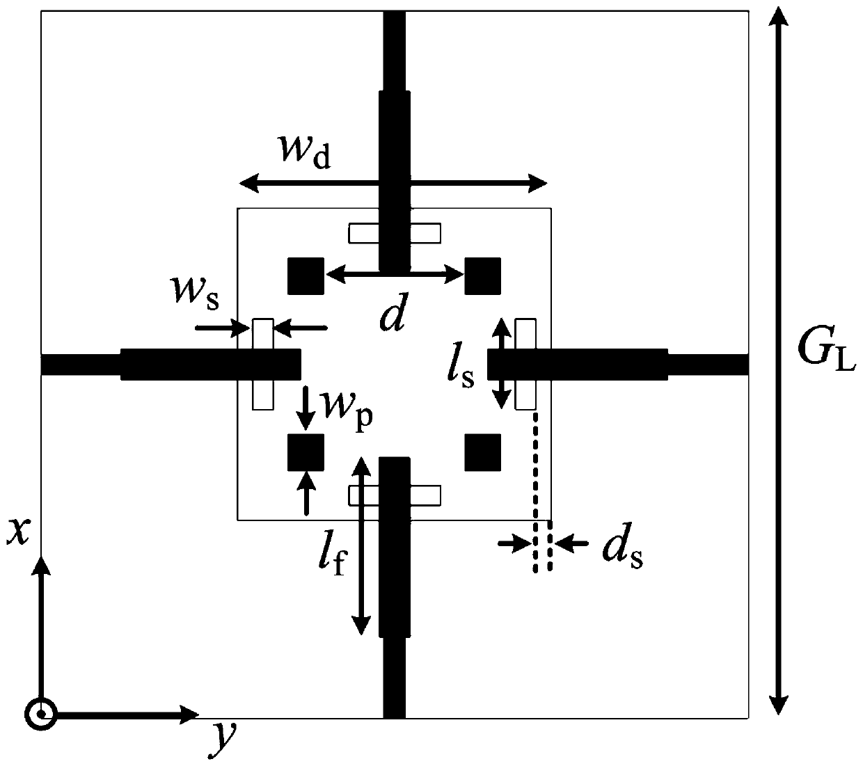
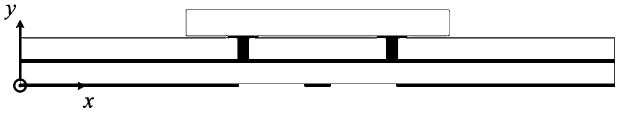
[0020] Such as Figure 1 to Figure 3 As shown, the high-gain differential dual-polarized dielectric patch antenna based on the high-order mode in this embodiment includes a square lower dielectric substrate 5, a metal reflective floor 4, an upper dielectric substrate 3 and a dielectric patch that are stacked sequentially from bottom to top. slice 1. In this example, dielectric patch 1 is a square ceramic patch with a dielectric constant of ε r2 = 90, loss tangent tanδ = 7×10 -4 , with a volume of w d x w d x h d . The dielectric patch is located at the center of the upper dielectric substrate 2, and the shape of the dielectric patch 1 is symmetrical along the two polarization directions of the antenna. In addition, the dielectric patch 1 may also be circular. The dielectric substrate used is Rogers RO4003, the dielectric constant...


PUM

PropertyMeasurementUnit
thicknessaaaaaaaaaa
dielectric lossaaaaaaaaaa

Abstract

The invention relates to a high-gain differential dual-polarized dielectric patch antenna based on a high-order mode. The antenna comprises a lower dielectric substrate, a metal reflection floor, an upper dielectric substrate and a dielectric patch which are stacked in sequence, wherein two pairs of microstrip feeders are arranged on the lower surface of the lower dielectric substrate; four metalpatches are arranged on the upper surface of the upper dielectric substrate; and the metal patches are connected with the metal reflection floor through metallized through holes. The metal patches andthe metalized through holes form grounding rods. The antenna works in two pairs of degenerate high-order mode TM121 and TM321 modes so as to realize high gain. The four grounding rods not only can move up the frequency of the TM121 mode to further improve the gain, but also can reduce the input impedance of the TM321 mode to enable the TM321 mode to be excited, thereby expanding the bandwidth ofthe antenna. TM121 and TM321 modes in respective directions are excited through two pairs of orthogonal differential feed structures, and the dual-polarized dielectric patch antenna is designed and has excellent performances of high isolation, high gain, low cross polarization and the like.

Description

technical field [0001] The invention relates to the technical field of wireless communication, in particular to a high-gain differential dual-polarization dielectric patch antenna based on a high-order mode. Background technique [0002] As two typical antennas in modern wireless communication systems, microstrip patch antennas and dielectric resonator antennas have been extensively studied and applied. Dielectric resonator antennas have several advantages over microstrip patch antennas, such as lower conductor loss, greater design freedom, and the ability to use more feeding schemes. In addition, benefiting from the multimodal nature of the dielectric resonator, the performance of the antenna can be significantly improved. On the one hand, the impedance bandwidth of the dielectric resonator antenna can be extended by combining higher-order modes. On the other hand, since the gain of the traditional dielectric resonator antenna is lower than that of the microstrip patch an...

Claims


Application Information

Patent Timeline
Patent Type & Authority Applications(China)
IPC IPC(8): H01Q9/04H01Q1/48H01Q1/38H01Q15/14
CPCH01Q1/38H01Q1/48H01Q9/0407H01Q9/0478H01Q9/0485H01Q15/14
Inventor 陈建新王雪颖唐世昌
Owner 江苏迅海智能科技有限公司
Why Eureka
Try Eureka