Micro-strip reflective array antenna

A reflect array antenna and microstrip technology, applied in antennas, slot antennas, antenna grounding devices, etc., can solve the problems of insufficient parallelism of the frequency characteristic curve, large cross-polarization component, and high cost, and achieve the parallelism of the unit frequency characteristic curve. Good, good phase shift curve linearity, easy to manufacture and process

Inactive Publication Date: 2018-07-13
XIDIAN UNIV
View PDF4 Cites 10 Cited by
  • Summary
  • Abstract
  • Description
  • Claims
  • Application Information

AI Technical Summary

Problems solved by technology

But, the weak point that this invention still exists: 1) unit structure is complicated, is unfavorable for processing; 2) this unit is double-layer structure, and cost is high
[0005] Literature Maurizio Bozzi, Simone Germani, and Luca Perregrini, "Performance Comparison of Different Element Shapes Used in Printed Reflectarrays," IEEE Antennas and Wireless Propagation Letters, 2003, Vol.2, pp.219–222 analyzed and compared several single-layer reflectarrays The performance of the unit, from which it can be seen that the general single-layer passive microstrip reflectarray unit has shortcomings: 1) The phase shift range of the unit is difficult to reach 360°; 2) The linearity of the phase shift curve is not enough, resulting in a large requirement for processing accuracy; 3 ) narrow bandwidth
However, the disadvantages that still exist in this invention are: due to the square ring structure used in the unit design, a large cross-polarization component will be introduced
[0007] To sum up, the current technical invention is facing three problems, one is the difficulty of processing and high cost caused by the complex structure of the unit, which limits the large-scale application of microstrip reflectarray antennas with complex structures; the other is the single-layer reflectarray The basic performance of the unit is insufficient, such as the phase shift range is difficult to reach 360°, the linearity of the phase shift curve is not enough, and the parallelism of the frequency characteristic curve is not enough, resulting in a decrease in the gain bandwidth of the single-layer microstrip reflectarray antenna; the third is that the single-layer reflectarray unit is in In the dual polarization state, a large cross-polarization component will be introduced, resulting in a large cross-polarization of the single-layer reflectarray antenna

Method used


Image

  • Micro-strip reflective array antenna
  • Micro-strip reflective array antenna
  • Micro-strip reflective array antenna

Examples


example 1

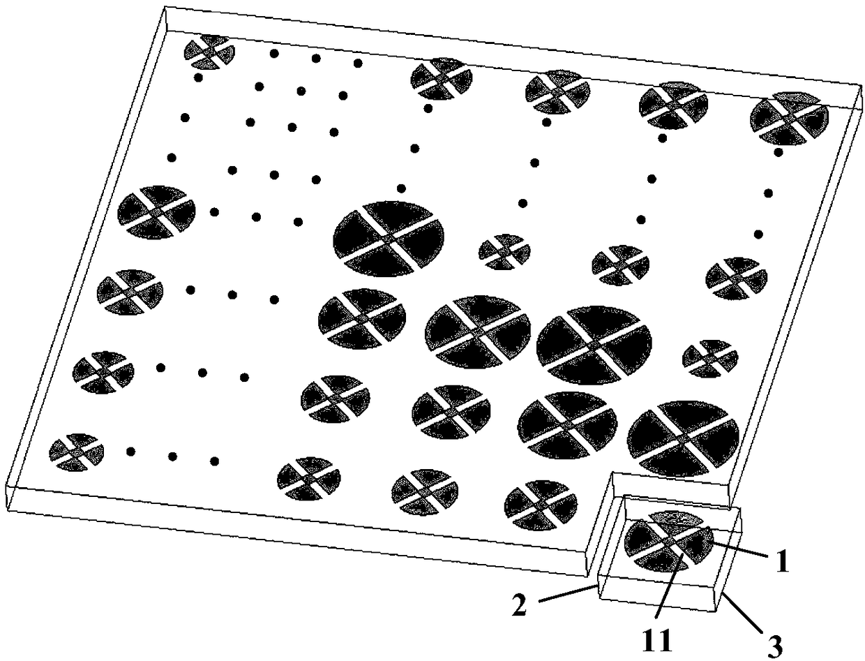
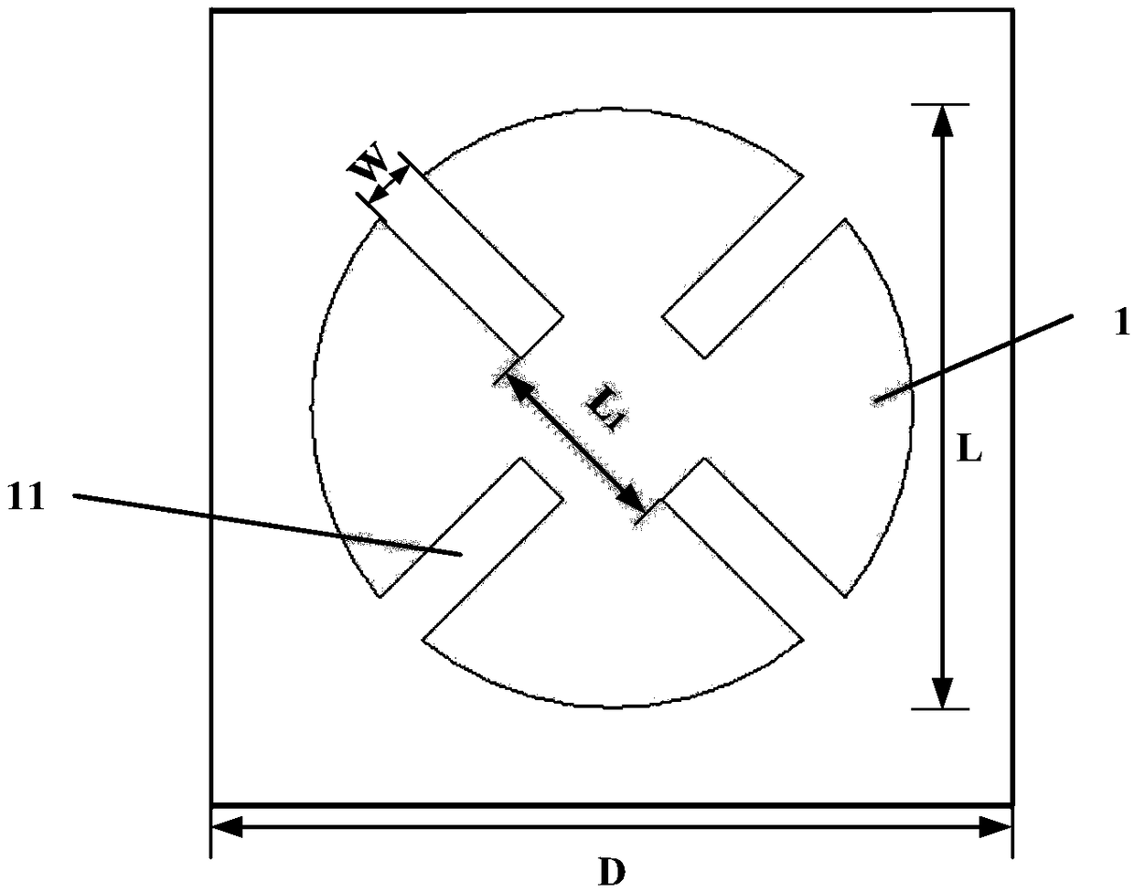
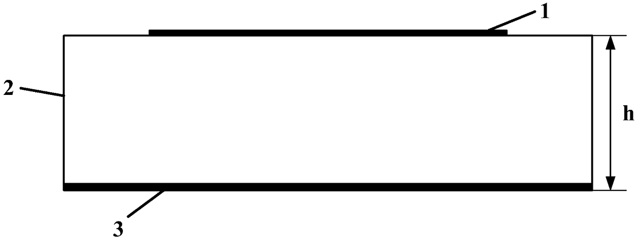
[0039] Example 1: A microstrip reflectarray antenna with an aperture distribution of 40mm×40mm.

[0040] refer to Figure 4 , in this embodiment, the aperture distribution of the microstrip reflectarray is 40mm×40mm, and it is composed of 100 reflectarray units of 10×10 arranged according to the interval D of 4mm. The diameter L of each unit is different, that is, it is set within 1 mm to 4 mm according to the change curve of reflection phase and diameter, the width W of each slit is 0.3 mm, and the distance L between two slits 1 is 0.4mm; the relative permittivity ε of the dielectric substrate is 3.66, and the thickness h is 1.118mm; the coordinates of the reflective array unit (x i ,y i ,z i ) range of values: -4.5D≤x i ≤4.5D, -4.5D≤y i ≤4.5D, zi =0, where D is the arrangement period of each unit; incident wave angle Reflected wave angle

example 2

[0041] Example 2: Microstrip reflectarray antenna with an aperture distribution of 28mm×28mm

[0042] refer to Figure 5 In this example, the microstrip reflectarray antenna with a caliber distribution of 28mm×28mm is composed of 64 reflectarray units of 8x8 arranged according to the interval D of 3.5mm. The diameter L of each unit is different, that is, it is set within 0.875mm to 3.5mm according to the change curve of reflection phase and diameter, the width W of each slit is 0.22mm, and the distance L between two slits 1 is 0.375mm; the relative permittivity ε of the dielectric substrate is 3.4, and the thickness h is 0.25mm; the coordinates of the reflective array unit (x i ,y i ,z i ) range of values: -3.5D≤x i ≤3.5D, -3.5D≤y i ≤3.5D, z i =0, where D is the arrangement period of each unit; incident wave angle Reflected wave angle

example 3

[0043] Example 3: Microstrip reflectarray antenna with an aperture distribution of 60mm×60mm

[0044] refer to Figure 6 , in this embodiment, the aperture distribution of the microstrip reflectarray is 60mm×60mm, and it is composed of 12×12 100 reflectarray units arranged according to the interval D of 5mm. The diameter L of each unit is different, that is, according to the change curve of reflection phase and diameter, it is set within 1.25mm~5mm, the width W of each slit is 0.36mm, and the distance L between two slits 1 is 0.5mm; the relative permittivity ε of the dielectric substrate is 3.8, and the thickness h is 2mm; the coordinates of the reflective array unit (x i ,y i ,z i ) range of values: -5.5D≤x i ≤5.5D, -5.5D≤y i ≤5.5D, z i =0, where D is the arrangement period of each unit; incident wave angle Reflected wave angle

[0045] Effect of the present invention can be further illustrated by following simulation:

[0046] 1. Simulation conditions

[0047] I...


PUM


Abstract

The invention discloses a micro-strip reflective array antenna, and mainly solves problems in the prior art that the structure is complicated and the bandwidth is narrower. The micro-strip reflectivearray antenna is formed by periodically arranging a plurality of horizontally and longitudinally uniformly arranged paster units. A reflecting phase of each paster unit is different, and an arrangement period D is 0.3-0.5 Lambda. Each unit successively comprises a paster (1), a medium substrate (2) and a floor (3) from top to bottom. The paster (1) uses a circular structure. The circular paster isprovided with two pairs of gaps (11). The two pairs of the gaps (11) are positioned at two ends of two mutual perpendicular diameter lines of the circle. The micro-strip reflective array antenna is capable of improving the gain bandwidth, simple in structure, smaller in cross-polarization, and good in unit frequency characteristic curve parallelism, and can be used for the electromagnetic wave regulation and control of a microwave band.

Description

technical field [0001] The invention belongs to the field of electromagnetic communication, and in particular relates to a single-layer circular slit microstrip reflection array unit, which can be used for electromagnetic wave regulation in microwave bands. Background technique [0002] In recent years, with the rapid development of mobile communication technology, both radar and communication systems expect antennas to have more functionality and adaptability. Microstrip antennas have been widely studied and applied due to their small size, light weight, low profile, and easy integration. Microstrip reflectarray antennas have some advantages of reflector antennas and large phased array antennas, and have been favored by researchers. favor. [0003] The microstrip reflectarray antenna is mainly composed of a series of microstrip patches and feed sources, but the traditional microstrip planar reflectarray antenna cannot meet the requirements of dual polarization and wide uni...

Claims


Application Information

Patent Timeline
Patent Type & Authority Applications(China)
IPC IPC(8): H01Q21/24H01Q13/10H01Q1/38H01Q1/48H01Q3/01
CPCH01Q1/38H01Q1/48H01Q3/01H01Q13/10H01Q13/106H01Q21/24
Inventor 李龙卢雨笑方遥易浩
Owner XIDIAN UNIV
Why Eureka
Try Eureka