
Inertial rotation piezoelectric motor

A technology of rotating pressure and electric motors, applied in electrical components, piezoelectric effect/electrostrictive or magnetostrictive motors, generators/motors, etc., can solve the problems of low motion efficiency, large friction damage, etc. High efficiency, large deformation and low noise

Active Publication Date: 2019-06-07
HEFEI UNIV OF TECH
View PDF5 Cites 6 Cited by
  • Summary
  • Abstract
  • Description
  • Claims
  • Application Information

AI Technical Summary

Problems solved by technology

[0003] In order to overcome the problems of large friction damage and low motion efficiency existing in the existing inertial impact piezoelectric motor, the present invention proposes an inertial rotation piezoelectric motor

Method used


Image

  • Inertial rotation piezoelectric motor
  • Inertial rotation piezoelectric motor
  • Inertial rotation piezoelectric motor

Examples


Embodiment Construction

[0032] The present invention will be further described through the embodiments below in conjunction with the accompanying drawings.

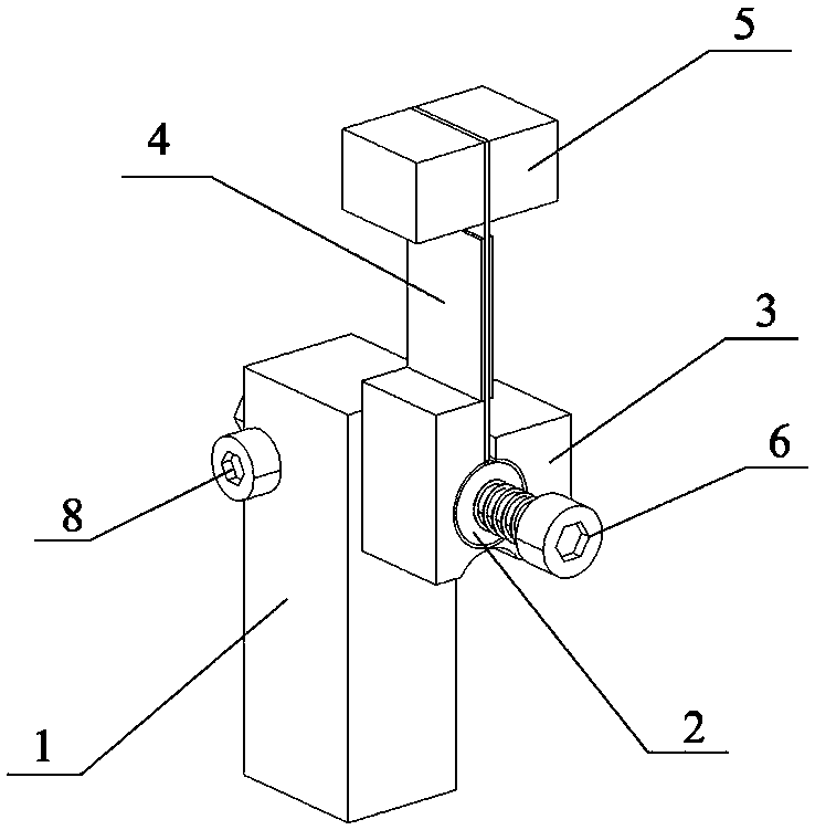
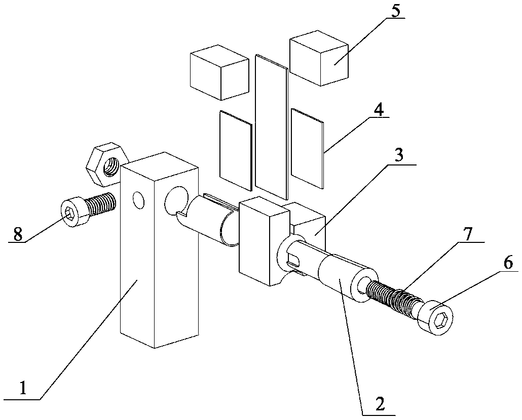
[0033] see figure 1 and figure 2 , an inertial rotary piezoelectric motor includes a base 1, a rotor mechanism and a pretension mechanism.

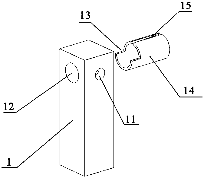
[0034] see image 3 , the base 1 is a square prism, and the top of the base 1 is provided with mounting holes 12 through the corresponding two sides, and the side surface of the base 1 corresponding to the mounting holes 12 is fixedly connected with the mounting pipe 14, and the pipe hole of the mounting pipe 14 is a conical hole. And the small-diameter end of the conical hole corresponds to the mounting hole 12 on the base 1, the mounting pipe 14 is in the shape of a cantilever, and the large-diameter end of the conical hole is an outer port. The other side of the upper part of the base 1 is provided with a threaded hole 11, and the threaded hole 11 and the mounting hole 12 are connected at 90 degrees...


PUM


Abstract

The invention relates to an inertial rotation piezoelectric motor. The inertial rotation piezoelectric motor comprises a base, a rotor mechanism and a pretightening mechanism, wherein the base comprises a quadrangular prism and a cantilever-shaped mounting pipe; the rotor mechanism comprises a rotor, a mounting plate, a pair of piezoelectric plates and a pair of mass blocks, the piezoelectric plates are fixedly arranged on the two side surfaces of the middle part of the mounting plate respectively, and the mass blocks are fixedly arranged on the two side surfaces of the upper part of the mounting plate; the pretightening mechanism comprises a pretightening shaft, a screw and a spring; in working hours, an electric signal with corresponding frequency is applied onto the piezoelectric plates, the mounting plate begins to swing, due to the existence of a flexible hinge, the mounting plate is of micro deflection around the flexible hinge, under the effect of the mass blocks, alternating conversion states of clamping and loosening appear, and the inertial rotation piezoelectric motor integrally rotates at a micro angle theta in the loosening state; and one-way rotational motion of the inertial rotation piezoelectric motor is realized through continuous motion. The friction loss during working is low, and the motion efficiency is improved by 5% to 10%.

Description

technical field [0001] The invention belongs to the technical field of precision driving and positioning, and in particular relates to an inertial rotation piezoelectric motor. Background technique [0002] Inertial impact piezoelectric motors are widely used, and have the characteristics of simple structure, easy miniaturization, easy control, and precise positioning; traditional inertial impact piezoelectric motors are generally driven by piezoelectric stacks, but the deformation of piezoelectric stacks is small. Poor tensile strength, unable to connect larger mass blocks, and high cost; inertial impact piezoelectric motors are divided into asymmetric drive signal type and asymmetric structure type, asymmetric drive signal type inertial impact piezoelectric motors are driven by sawtooth waves In order to obtain the asymmetry of the acceleration during the reciprocating process of the mover or the stator, but the inertial impact piezoelectric motor driven by the sawtooth wa...

Claims


Application Information

Patent Timeline
IPC IPC(8): H02N2/10
Inventor 贺良国徐磊李新宇朱立红潘巧生葛新方楚宇恒郝赛程子阳张勇
Owner HEFEI UNIV OF TECH
Learn More