
A sky hall real scene real-time display method

A technology of astronomical phenomena and real scenes, which is applied in the field of real-time display of real-time scenes in the astronomical hall, can solve the problems of less realism and mystery in the starry sky, and achieve the effect of increasing richness, increasing interest, and facilitating popularization

Active Publication Date: 2019-06-07
LIGHT SPEED VISION BEIJING
View PDF7 Cites 2 Cited by
  • Summary
  • Abstract
  • Description
  • Claims
  • Application Information

AI Technical Summary

Problems solved by technology

[0005] However, the existing planetarium is also affected by multimedia technology, so that the images played in the planetarium are mostly virtual images pre-synthesized through multimedia technology. Although the content is wonderful and diverse, it also lacks the realism and Mystery

Method used


Image

  • A sky hall real scene real-time display method
  • A sky hall real scene real-time display method
  • A sky hall real scene real-time display method

Examples


Embodiment 1

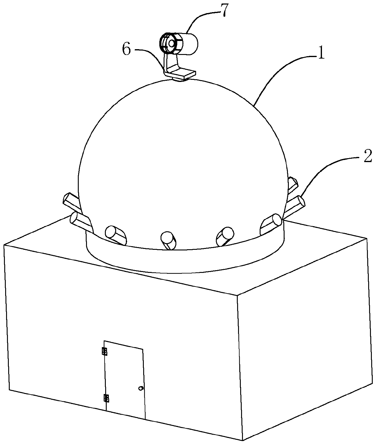
[0032] refer to figure 1 , a real-time display method of a planetarium, wherein the planetarium 1 includes a circular vertical wall and a hemispherical zenith 11 arranged on the circular vertical wall.

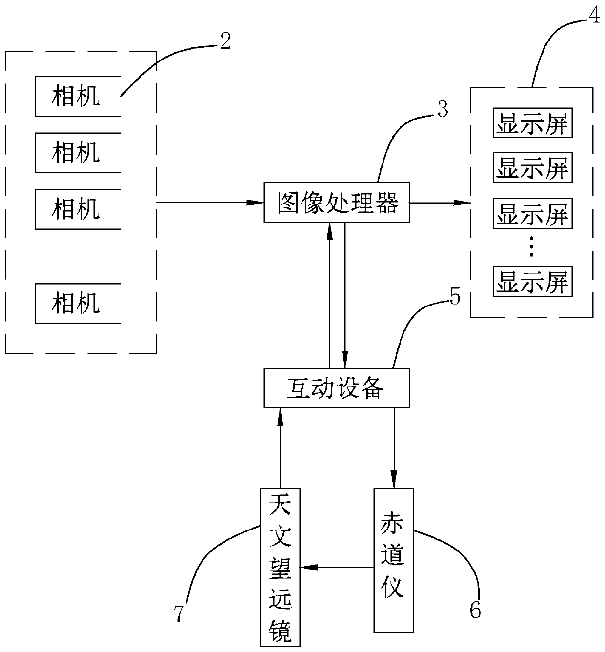
[0033] refer to figure 2 The real-time display method of the space hall 1 includes setting multiple groups of cameras 2 outside the space hall 1, and the cameras 2 are connected to the image display device 4 located in the exhibition area through an image processor 3 located in the exhibition area. The shooting angles of the camera 2 are different and cover the whole day. The camera 2 shoots the astronomical phenomenon to generate a captured image, and the image processor 3 selects and intercepts the captured image of a preset position in the output captured image of each camera 2, and stitches the captured image into a For the all-sky image corresponding to the all-sky phenomenon, the image processor 3 transmits the all-sky image to the image display device 4 for display in...

Embodiment 2

[0040] The difference between this embodiment and the first embodiment is that the cameras 2 are concentrated and fixed in a square array above the hemispherical zenith 11 of the planetarium 1 (not shown in the figure). Here, it is not limited to a square array, as long as multiple groups of cameras 2 are arranged in a concentrated manner, it is within the description scope of this embodiment. The centralized arrangement of the cameras not only makes the cameras 2 closely arranged, but also increases the number of cameras 2 that can be arranged, making the collected images clearer.

Embodiment 3

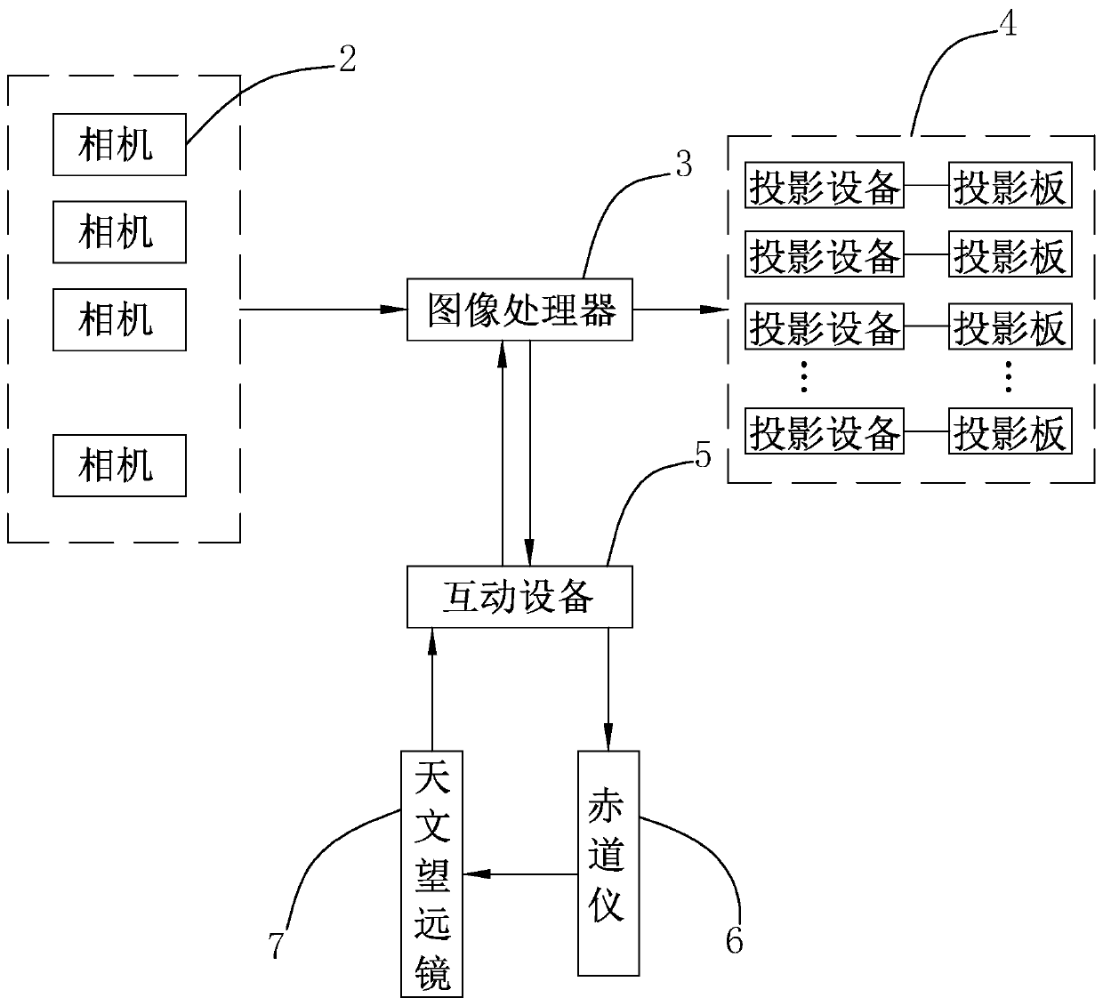
[0042] The difference between this embodiment and Embodiment 1 is that: image 3 As shown, the image display device 4 includes a plurality of projection boards spliced ​​together to form a dome, and a projection device arranged in the planetarium 1 and corresponding to the projection boards one by one. The projection equipment is set as a projector, and the center of the floor in the planetarium 1 is provided with a projection table on which a projector is installed, and multiple projectors are installed on the projection table to realize the projection on the dome. Here, the projection table is preferably a spherical projection table, and a plurality of projectors are evenly distributed on the upper surface of the spherical projection table.


PUM


Abstract

The invention discloses a sky hall real scene real-time display method. a plurality of groups of cameras are arranged outside the planetarium; The camera is connected to an image display device located in the exhibition place through an image processor located in the exhibition place. the cameras outside the same planetarium have different shooting angles and cover the whole day; wherein the cameras shoot celestial images to generate shot images, the image processor selects and intercepts intercepted images at preset positions in the shot images output by each camera and splices the intercepted images into all-day images, and the image processor transmits the all-day images to the image display device in real time to be displayed. According to the technical scheme, the sky real scene can be displayed in real time, real changes such as relative size, position and brightness of stars in satellites and the whole starry sky can be watched conveniently, and therefore the reality of the playing content of the planetarium is enhanced, and popularization of astronomical knowledge is facilitated.

Description

technical field [0001] The invention relates to astronomical shooting, in particular to a real-time real-time display method of a planetarium. Background technique [0002] Endless space, because of its mystery and unknown, has always attracted people to continue to explore, and astronomical research has always been an important symbol of a country's technological and cultural development. In order to facilitate astronomy enthusiasts and astronomers to explore the mysteries of the starry sky, and to realize the popularization of astronomical knowledge, some equipment used in astronomical research has slowly entered people's lives. [0003] With the development of multimedia technology, the popularization of astronomical knowledge requires corresponding intelligent equipment to dynamically demonstrate the state of celestial bodies. For this reason, the Astronomical Hall came into being. [0004] Most of the existing astronomical halls include a dome screen. Through the proj...

Claims


Application Information

Patent Timeline
IPC IPC(8): H04N7/18H04N9/31H04N5/247
Inventor 邱虹云
Owner LIGHT SPEED VISION BEIJING
Learn More