A visual beauty instrument with rotatable head
A beauty instrument and head technology, applied in the field of visual beauty instrument, can solve the problems of single function, unstable camera process, electromagnetic interference of camera, etc., and achieve the effect of avoiding mutual interference.
- Summary
- Abstract
- Description
- Claims
- Application Information
AI Technical Summary
Problems solved by technology
Method used
Image
Examples
Embodiment 1
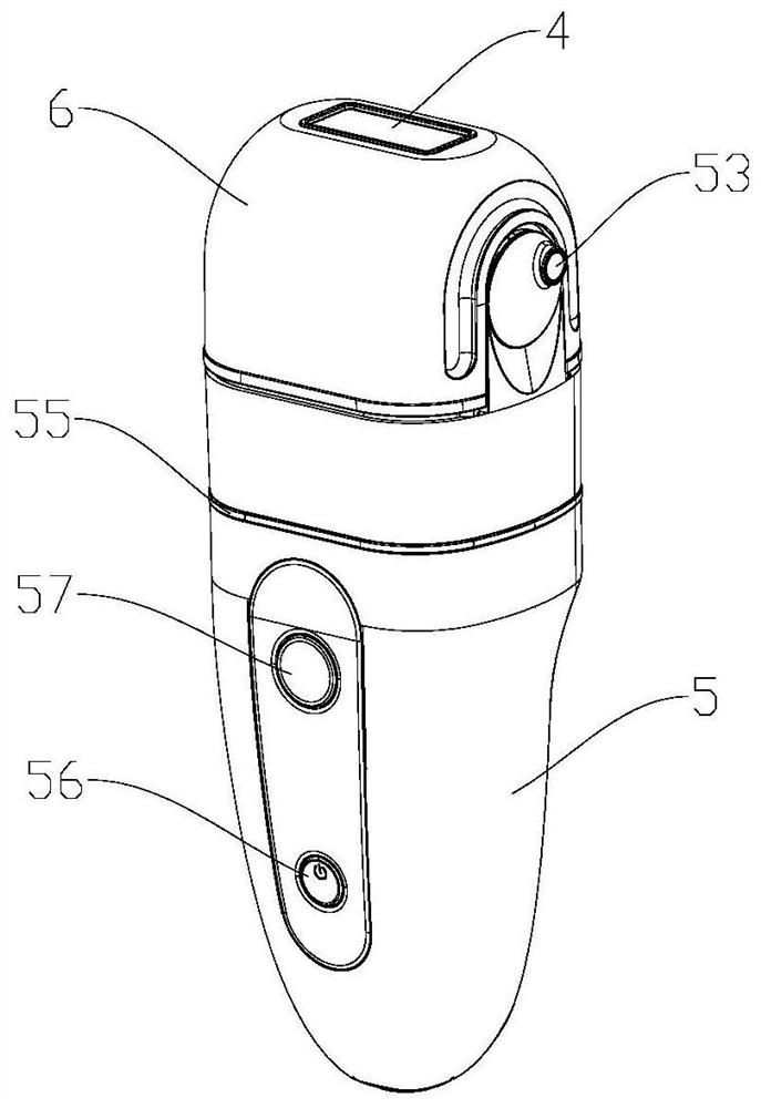
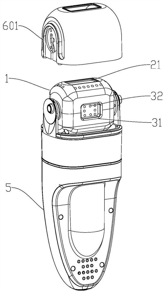
[0049] Such as figure 1 , figure 2 and Figure 6 As shown, a visual beauty instrument with a rotatable head includes a beauty mechanism 2 and a camera 3. The beauty mechanism 2 and the camera 3 are arranged on different sides of the rotating part 1 of the head of the beauty instrument. When the rotating part 1 rotates back and forth , switch the beauty mechanism 2 or the camera 3 towards the exposure window 4 of the beauty instrument.
[0050]In each of the following embodiments, the beauty mechanism 2 is selected as a xenon tube, which has the effect of hair removal, but the xenon management cannot be interpreted as limiting the scope of the invention patent. In other embodiments, the beauty mechanism can also be a radio frequency component. High-frequency radio frequency electromagnetic waves heat the dermis of the skin, which has the effect of removing wrinkles; the beauty mechanism can also be a micro-current emitting component, which stimulates the skin and muscles thr...
Embodiment 2
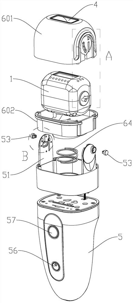
[0057] Such as image 3 , Figure 4 and Figure 5 As shown, this embodiment provides a visual beauty instrument with a rotatable head, and its structure is the same as that of the first embodiment, the difference is that the visual beauty instrument with a rotatable head provided by this embodiment also includes a hand-held part 5 and a movable cover 6 , both sides of the top of the hand-held part 5 are provided with rotating shaft brackets 51, the outer surface of the side wall of the movable cover 6 is slidably connected with the rotating shaft bracket 51, the inner surface of the side wall of the movable cover 6 is rotationally connected with the rotating part 1, and the movable cover 6 can be rotated along the handle. The rotating shaft brackets 51 on both sides of the top end of the part 5 move up and down, and the rotating part 1 rotates back and forth along with the movable cover 6 moving up and down.
[0058] Such as Figure 6 , Figure 7 and Figure 8 As shown, s...
Embodiment 3
[0069] Such as Figure 4 , Figure 5 and Figure 8 As shown, this embodiment provides a visual beauty instrument with a rotatable head. Its structure is the same as that of Embodiment 2, the difference is that the outer wall of the movable cover 6 is provided with a sliding bar 63, and the inner wall of the rotating shaft bracket 51 is provided with a sliding bar. The bar 63 fits into the chute 52 . The movable cover 6 moves up and down on the rotating shaft bracket 51 through the sliding bar 63 and the slide groove 52 .
[0070] The rotating shaft bracket 51 is provided with a movable buckle 53 and a window 54, and the movable buckle 53 is provided with a pair of outwardly barbed hook feet 531, which can be buckled on the inwall of the rotating shaft bracket 51 to prevent the movable buckle 53 from falling; On the slot 52, the sliding bar 63 is provided with a notch 631 facing the window 54, and the notch 631 divides the sliding bar 63 into two parts. The window 54 is ope...
PUM
 Abstract
Description
Claims
Application Information
 - R&D
- Intellectual Property
- Life Sciences
- Materials
- Tech Scout
- Unparalleled Data Quality
- Higher Quality Content
- 60% Fewer Hallucinations
Browse by: Latest US Patents, China's latest patents, Technical Efficacy Thesaurus, Application Domain, Technology Topic, Popular Technical Reports.
© 2025 PatSnap. All rights reserved.Legal|Privacy policy|Modern Slavery Act Transparency Statement|Sitemap|About US| Contact US: help@patsnap.com


