Intramedullary fixation device with shape locking interface

A locked state, recessed part technology, applied in the direction of internal fixator, fixator, internal bone synthesis, etc., can solve the problems of increased risk of infection, increased blood loss, and prolonged healing time

Pending Publication Date: 2019-06-07
THE UNIV OF BRITISH COLUMBIA +1
View PDF9 Cites 0 Cited by
  • Summary
  • Abstract
  • Description
  • Claims
  • Application Information

AI Technical Summary

Problems solved by technology

Invasive open surgery can lead to increased blood loss, increased risk of in

Method used


Image

  • Intramedullary fixation device with shape locking interface
  • Intramedullary fixation device with shape locking interface
  • Intramedullary fixation device with shape locking interface

Examples


Embodiment Construction

[0026] In the following detailed description, reference is made to the accompanying drawings, which form a part hereof. In the drawings, similar symbols typically identify similar components, unless context dictates otherwise. In the detailed description, the illustrative embodiments described in the drawings and claims are not meant to be limiting. Other embodiments may be utilized, and other changes may be made, without departing from the spirit or scope of the subject matter presented here. It is to be readily understood that the aspects of the present disclosure as generally described herein and illustrated in the drawings may be arranged, substituted, combined and designed in various configurations, all of which are expressly contemplated and constitute an integral part of the present disclosure. part.

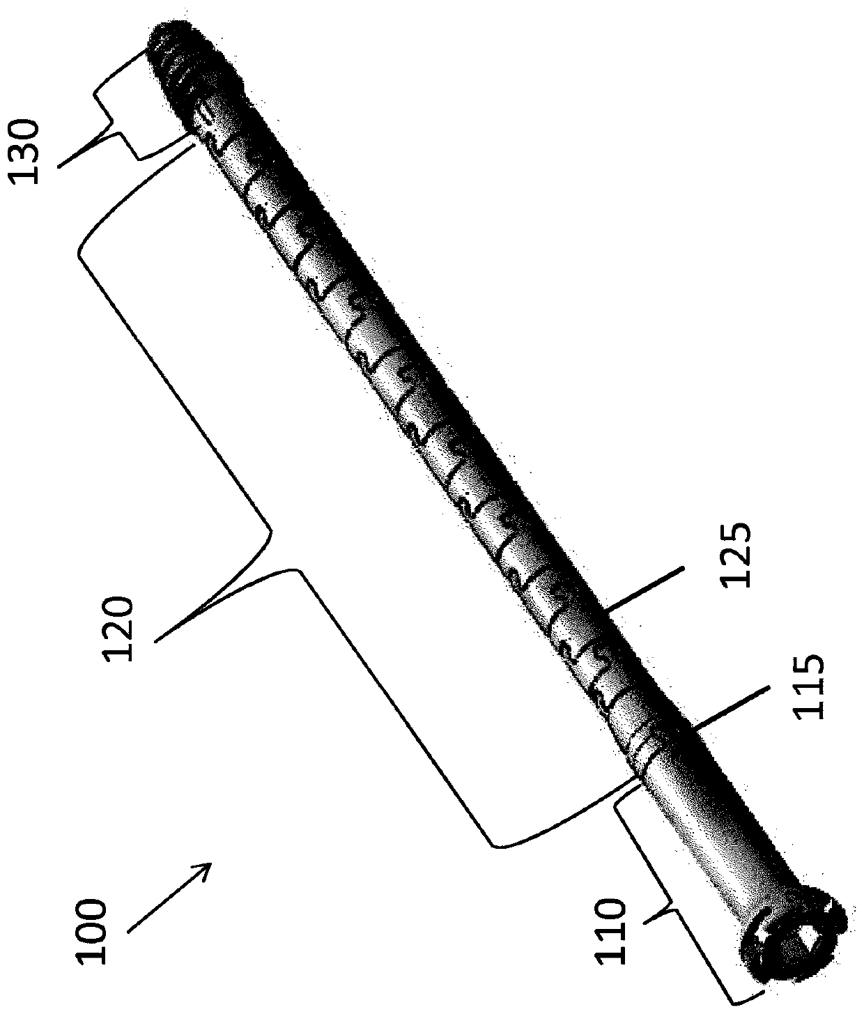
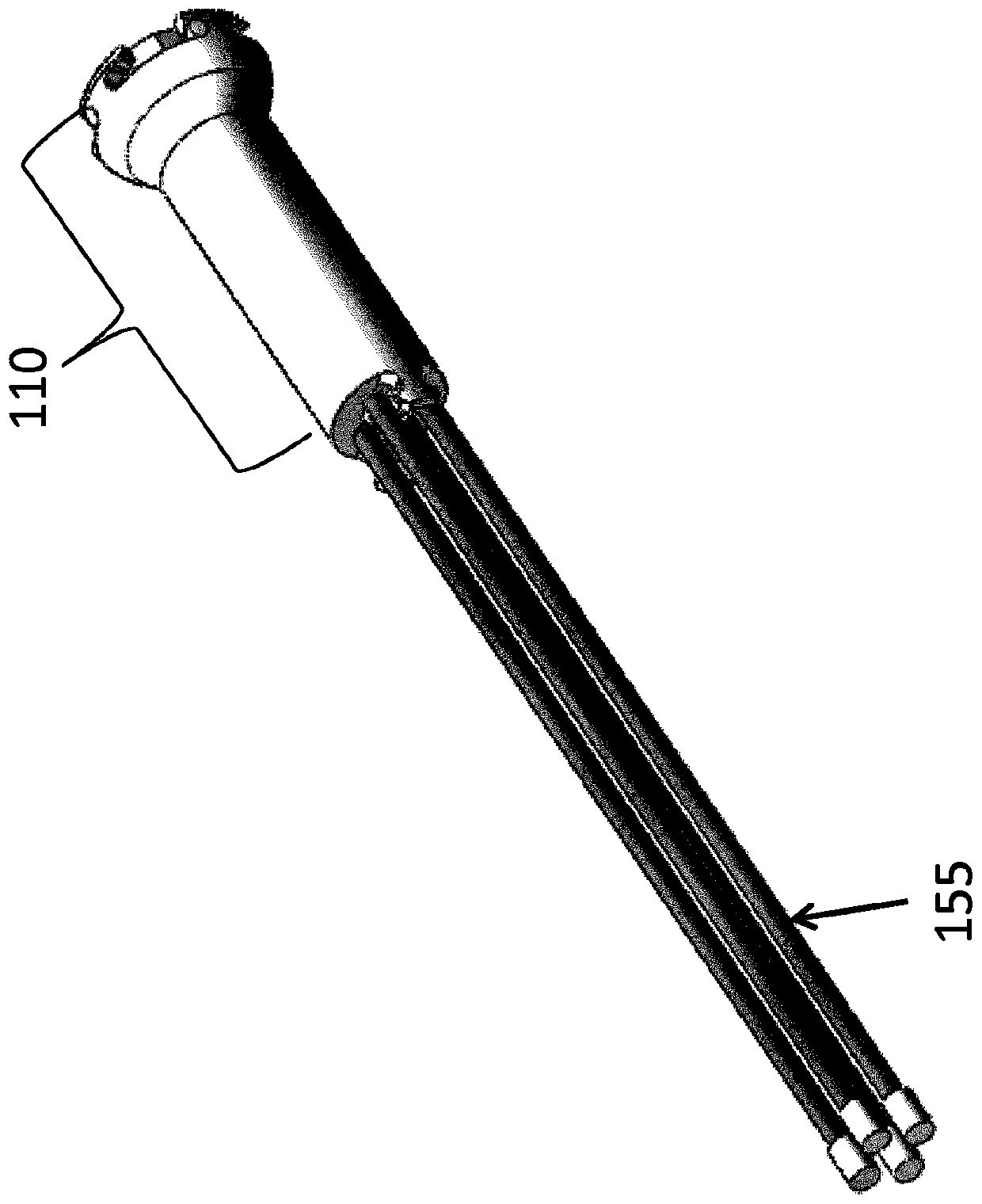
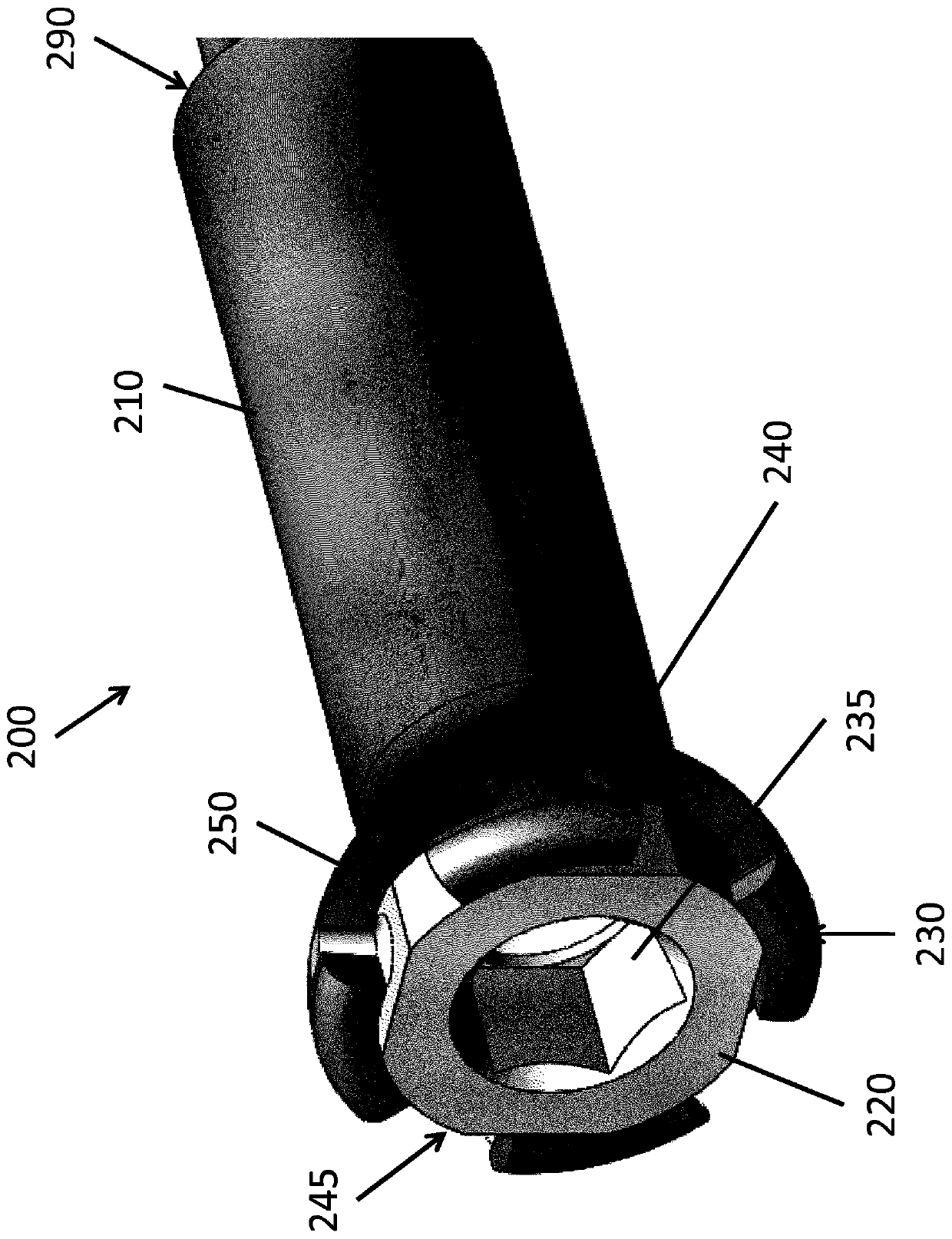
[0027] Various embodiments are described herein for immobilizing a fractured or broken bone. The systems, devices and methods described herein can be used on long and ...


PUM


Abstract

Implantable devices for fixation of curved bones such as the pelvic ring pubic symphysis and acetabulum, and methods for the use of the devices are disclosed. The implantable devices are convertible between a flexible state and a rigid state using a shape locking section. The implantable devices further include a main body and a distal bone interface. In a flexible state, the devices may be inserted along, and conform to a curved pathway, and in the rigid state, the devices may support the mechanical loads required to fixate a fracture.

Description

Background technique [0001] The following descriptions are provided to aid the reader in understanding. None of the information presented or references cited is admitted to be prior art. [0002] Fractures can occur in straight bones such as the femur or in curved bones such as the pelvic bone. Repairing a fracture usually involves two steps: fracture reduction and fracture fixation. Reduction is the step of reducing the fracture by minimizing the distance between the bone fragments and anatomically aligning the bone to minimize deformity after healing. Both surgical and non-surgical reduction methods exist. Immobilization, the step of keeping fracture fragments mechanically stable and close together to promote bone healing, can take weeks or longer, depending on the type of fracture, bone type, and general health of the patient suffering the injury. [0003] Immobilizing the fracture fragments in a mechanically stable manner to eliminate motion across the fracture site ma...

Claims


Application Information

Patent Timeline
IPC IPC(8): A61B17/58A61B17/68A61B17/72A61B17/84A61B17/86
CPCA61B17/8625A61B17/8685A61B17/7208A61B17/7233
Inventor D·T·斯廷森C·A·泰勒
Owner THE UNIV OF BRITISH COLUMBIA
Why Eureka
Try Eureka