Milling cutter

A milling cutter and blade technology, applied in the field of milling cutters, can solve the problems of difficulty in controlling the rotation angle of the blade, waste of the four side walls of the blade, and inability to make full use of the blade, so as to ensure the strength of the blade, improve the cutting effect, and prolong the service life. Effect

Active Publication Date: 2019-06-11
杭州超尔切削工具有限公司
View PDF12 Cites 6 Cited by
  • Summary
  • Abstract
  • Description
  • Claims
  • Application Information

AI Technical Summary

Problems solved by technology

[0003] The blades used in existing milling cutters are generally square or round. The disadvantage of the square blade is that the four corners of the general blade are blades. During the cutting process, the four blades can be switched for cutting. However, due to The workpiece is a metal piece, and the blade is easy to wear during cutting. The square blade can only switch four blades for cutting work. This arrangement is undoubtedly a waste of the four side walls of the blade; while the edge of the circular blade is a whole The cutting edge, after the cutting edge is partially worn, the circular blade can be rotated to switch the cutting edge to cut the workpiece, so that it can increase the usable times of the cutting edge and prolong the service life of the cutting edge; however, because the cutting edge is set in a circular shape, it is difficult to control the movement of the cutting edge during the rotation process. The angle of rotation may cause it to fail to make full use of its blade for cutting, or continue to use part of the worn blade for cutting during the rotation process, affecting its cutting effect

Method used


Image

  • Milling cutter
  • Milling cutter
  • Milling cutter

Examples


Embodiment 2

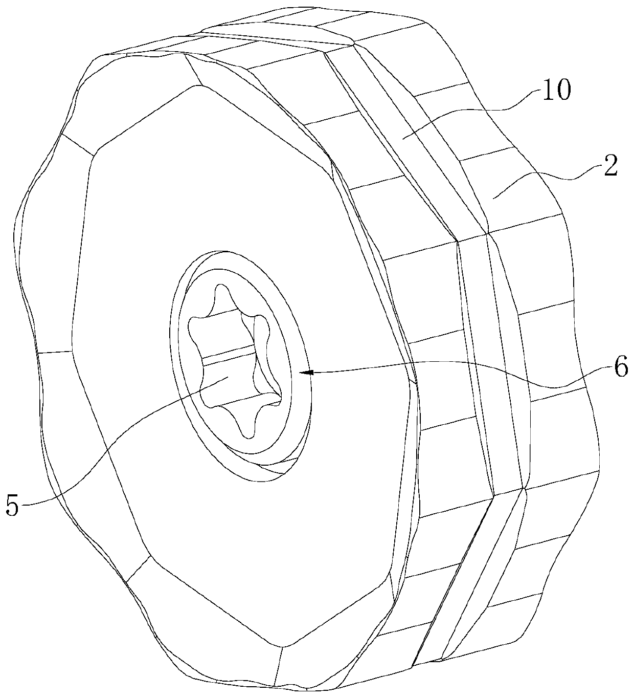
[0044] Embodiment 2: refer to image 3 , the difference from Embodiment 1 is that: the outer wall of one end of the above-mentioned insertion rod 9 in the insertion groove 8 is provided with a section of external thread, and the inner wall of the insertion groove 8 is provided with an internal thread that cooperates with the external thread of the insertion rod 9; A turning slot (not shown in the figure) for inserting and rotating a screwdriver is provided on the end surface of the inserting rod 9 facing outside the inserting slot 8 .

[0045] The implementation principle of this embodiment is: to turn the blade 2, first use a screwdriver to rotate the two insertion rods 9 out of the insertion slot 8, and then use a screwdriver to loosen the locking bolt 5, and then manually drive the blade 2 to rotate , make it change the cutting edge to cut the workpiece, and then thread the inserting rod 9 into the inserting groove 8 to position the angle of the blade 2, and finally drive t...


PUM


Abstract

The invention relates to a milling cutter. The milling cutter comprises a cutter holder and blades; each blade is arranged in a substantially-circular polygonal shape; each edge of each blade is provided with a cutting edge; the cutter holder is provided with a plurality of mounting grooves corresponding to the blades; a locking bolt matched with the cutter base in a threaded mode is inserted intoand connected with the middle of each blade; the two side walls of each mounting groove are provided with insertion-connecting grooves correspondingly; the cross section of the insertion-connecting grooves are in a large semicircular shape; insertion-connecting rods are arranged in the insertion-connecting grooves; the side walls of the blades are provided with abutting grooves allowing the insertion-connecting rods to be inserted into and connected with correspondingly; and the side walls of the blades do not abut against the inner walls of the mounting grooves when the insertion-connectingrods are inserted into and connected with the abutting grooves. The milling cutter has the effect that the blade is positioned while the usable time of the cutting edges of the blades is ensured to the greatest extent.

Description

technical field [0001] The invention relates to the technical field of machining cutters, in particular to a milling cutter. Background technique [0002] At present, milling cutters are rotary cutters with one or more teeth for milling. When working, each knife tooth cuts off the allowance of the workpiece intermittently in turn. [0003] The blades used in existing milling cutters are generally square or round. The disadvantage of the square blade is that the four corners of the general blade are blades. During the cutting process, the four blades can be switched for cutting. However, due to The workpiece is a metal piece, and the blade is easy to wear during cutting. The square blade can only switch four blades for cutting work. This arrangement is undoubtedly a waste of the four side walls of the blade; while the edge of the circular blade is a whole The cutting edge, after the cutting edge is partially worn, the circular blade can be rotated to switch the cutting edge...

Claims


Application Information

Patent Timeline
Patent Type & Authority Applications(China)
IPC IPC(8): B23C5/08B23C5/20B23C5/22
Inventor 卜学军李朦特陈燕楠
Owner 杭州超尔切削工具有限公司
Why Eureka
Try Eureka