Photovoltaic energy storage charging direct current micro-grid control method

A technology of DC micro-grid and control method, which is applied in the direction of load balance, charging stations, vehicle energy storage, etc. in the DC network, and can solve the problems affecting the peak-valley balance of the power grid, the impact of the power grid, and the threat to the stable operation of the power grid, so as to ensure stability Reliable operation, maintaining stable operation, and improving reliability and robustness

Active Publication Date: 2019-06-11
TSINGHUA UNIV
View PDF7 Cites 6 Cited by
  • Summary
  • Abstract
  • Description
  • Claims
  • Application Information

AI Technical Summary

Problems solved by technology

[0002] In 2030, the sales of new energy vehicles in my country will reach 40%-50% of the total sales of vehicles in my country, and the number of vehicles will reach 80 million to 100 million vehicles, and the energy of these 80 million to 100 million electric vehicle batteries will reach About 5 billion kilowatt-hours of electricity, so the high-power charging of large-scale electric vehicles is bound to bring a huge impact on the power grid, affecting the peak-valley balance of the power gri

Method used


Image

  • Photovoltaic energy storage charging direct current micro-grid control method
  • Photovoltaic energy storage charging direct current micro-grid control method
  • Photovoltaic energy storage charging direct current micro-grid control method

Examples


Embodiment Construction

[0034] The present invention proposes a control method for optical storage charging DC microgrid, and the present invention will be further described in detail below in conjunction with the accompanying drawings and specific embodiments. It should be understood that the specific examples described here are only used to explain the present invention and not to limit the present invention.

[0035] The present invention proposes a method for controlling a DC microgrid for optical storage charging, which includes the following steps:

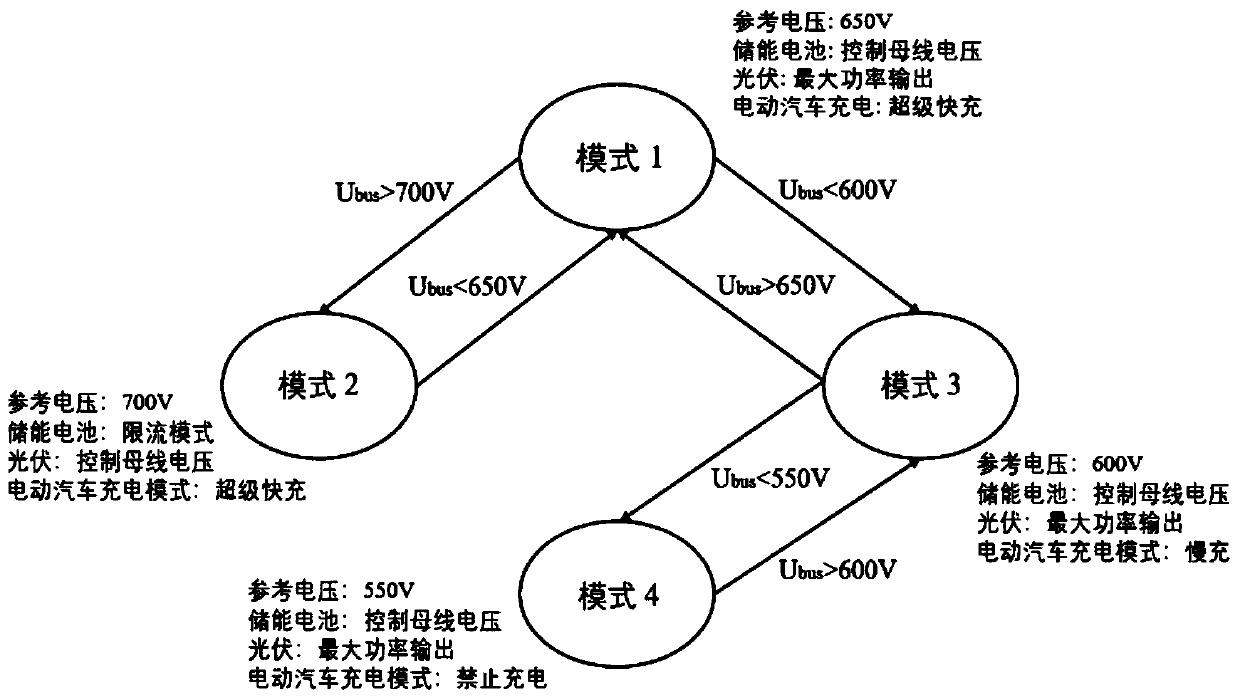
[0036] 1) Determine the DC bus voltage and select the control mode of the DC microgrid:

[0037] If the DC bus voltage is greater than 600V and less than 700V, then enter the control mode 1 of step 2);

[0038] If the DC bus voltage is greater than or equal to 700V, then enter the control mode 2 of step 3);

[0039] If the DC bus voltage is greater than 550V and less than or equal to 600V, then enter the control mode 3 of step 4);

[0040] If the ...


PUM


Abstract

The invention provides a photovoltaic energy storage charging direct current micro-grid control method, and belongs to the field of direct current micro-grid control. According to the photovoltaic energy storage charging direct current micro-grid control method, direct current busbar voltage is firstly determined, and a control mode of a direct current micro-grid is chosen; in mode 1, a maximum power tracking output mode is adopted in a photovoltaic battery, a constant voltage mode is adopted in an energy storage battery to control the busbar voltage, and a super-fast-charge/fast-charge mode is adopted in an electric automobile; in mode 2, a constant voltage mode is adopted in the photovoltaic battery to control the busbar voltage, a current limiting charging mode is adopted in the energystorage battery, and the super-fast-charge/fast-charge mode is adopted in the electric automobile; in mode 3, the maximum power tracking output mode is adopted in the photovoltaic battery, a current limiting constant voltage mode is adopted in the energy storage battery to control the busbar voltage, and a slow charging mode is adopted in charging of the electric automobile; and in mode 4, the state of the photovoltaic battery and the state of the energy storage battery are the same with the mode 3, and a blocking mode is adopted in charging of the electric automobile. According to the photovoltaic energy storage charging direct current micro-grid control method, the busbar voltage can be controlled in all sorts of situations, and stable operation of a photovoltaic energy storage chargingdirect current micro-grid is guaranteed.

Description

technical field [0001] The invention belongs to the field of direct current microgrid control, and in particular relates to a method for controlling an optical storage charging direct current microgrid. Background technique [0002] In 2030, the sales of new energy vehicles in my country will reach 40%-50% of the total sales of vehicles in my country, and the number of vehicles will reach 80 million to 100 million vehicles, and the energy of these 80 million to 100 million electric vehicle batteries will reach Therefore, the high-power charging of large-scale electric vehicles is bound to have a huge impact on the power grid, affecting the peak-valley balance of the power grid and threatening the stable operation of the power grid. As a new type of distributed power distribution organization and energy structure, microgrid can not only alleviate the impact of large-scale electric vehicle charging on the large power grid, but also adapt to the characteristics of randomness and...

Claims


Application Information

Patent Timeline
IPC IPC(8): B60L53/62B60L53/51H02J1/14
CPCY02T10/70Y02T10/7072Y02T90/12
Inventor 王烁祺卢兰光马克西姆张宝迪欧阳明高邢伟
Owner TSINGHUA UNIV
Why Eureka
Try Eureka