High water head water pump turbine rotating wheel double sealing pressure decreasing structure

A water pump turbine and high water head technology, which is applied in hydroelectric power generation, mechanical equipment, engine components, etc., can solve the problems of safe and stable operation of theoretical pressure, high pressure and luffing units, and achieve the reduction of alternating stress and the amplitude of water pressure fluctuations , the effect of reducing water pressure

Inactive Publication Date: 2019-06-11
HARBIN ELECTRIC MASCH CO LTD +1
View PDF4 Cites 0 Cited by
  • Summary
  • Abstract
  • Description
  • Claims
  • Application Information

AI Technical Summary

Problems solved by technology

[0005] The technical problem to be solved by the present invention is to provide a high-head water pump turbine runner for the theoretical pressure between the upper crown and the top cover may be too high and the pressure amplitude may be too large when switching between different working conditions, which may affect the safe and stable operation of the unit. Double-seal decompression structure for high head water pump turbine runner

Method used


Image

  • High water head water pump turbine rotating wheel double sealing pressure decreasing structure
  • High water head water pump turbine rotating wheel double sealing pressure decreasing structure
  • High water head water pump turbine rotating wheel double sealing pressure decreasing structure

Examples


specific Embodiment approach

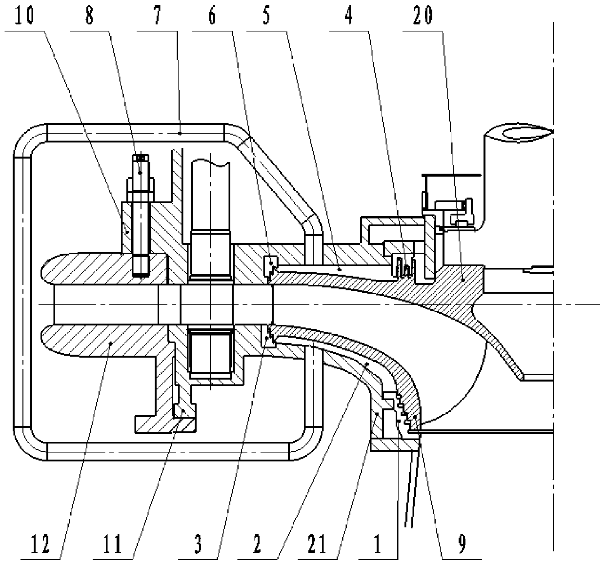
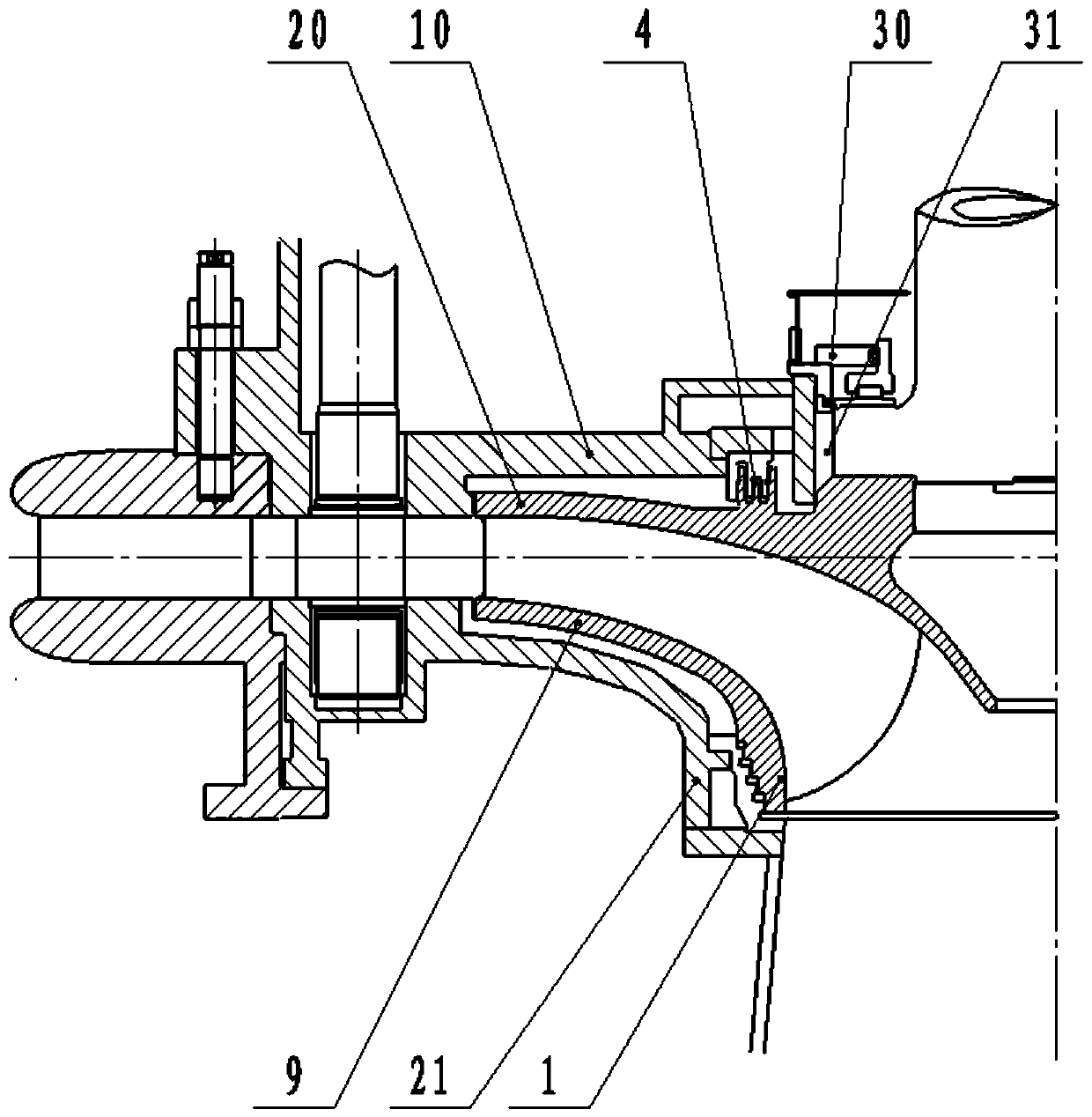
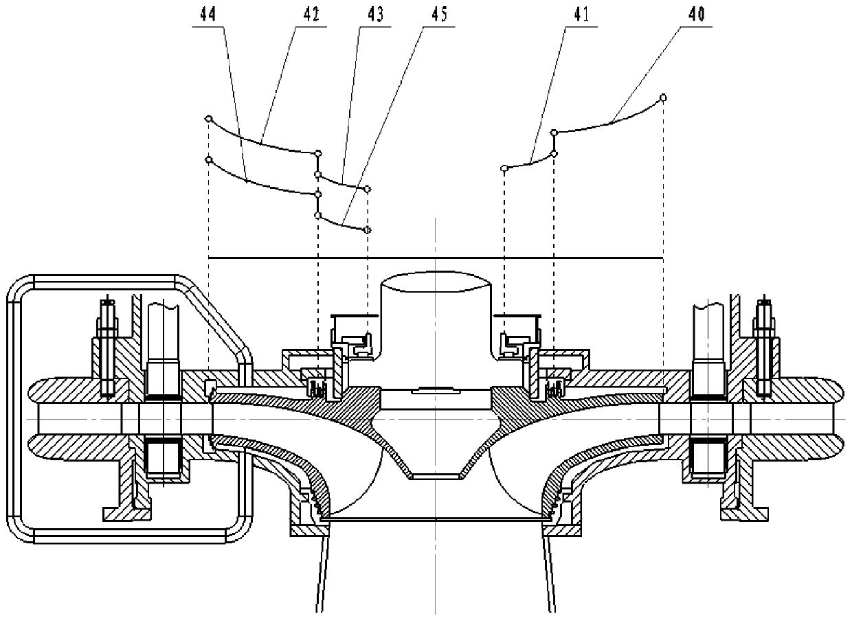
[0020] Specific implementation methods: such as Figure 1-3 As shown, two sets of anti-leakage ring sealing devices 6 and 3 are respectively arranged between the upper crown 20 and the top cover 10 of the runner and between the lower ring 9 and the base ring 21, that is, the upper crown outer diameter is set at the radial maximum diameter of the upper crown 20. The anti-leakage ring 6, the outer anti-leakage ring 3 of the lower ring is set at the radial maximum diameter of the lower ring 9, the outer anti-leakage ring 6 of the upper crown and the outer anti-leakage ring 3 of the lower ring have equal damping, and the lower ring 9 on the low pressure side of the runner is the smallest The inner leak stop ring 1 of the lower ring is set at the diameter, and the damping of the inner leak stop ring 1 of the lower ring is smaller than the damping of the outer leak stop ring 3 of the lower ring. The inner stop ring 4 of the upper crown, the outer stop ring 6 of the upper crown and t...


PUM


Abstract

The invention discloses a high water head water pump turbine rotating wheel double sealing pressure decreasing structure. The maximum diameter position of a rotating wheel upper crown (20) in the radial direction is provided with an upper crown outer leakage stopping ring (6); the maximum diameter position of a lower ring (9) in the radial direction is provided with a lower ring outer leakage stopping ring (3); the upper crown outer leakage stopping ring (6) and the lower ring outer leakage stopping ring (3) are equal in damping; the minimum diameter position of the portion, on the low pressure side of a rotating wheel, of the lower ring (9) is provided with a lower ring inner leakage stopping ring (1); damping at the position of the lower ring inner leakage stopping ring (1) is smaller than that at the position of the lower ring outer leakage stopping ring (3); the diameter positions of the rotating wheel upper crown (20) and the lower ring inner leakage stopping ring (1) are providedwith an upper crown inner leakage stopping ring (4); and the upper crown outer leakage stopping ring (6) and the lower ring outer leakage stopping ring (3) are the same in diameter. The high water head water pump turbine rotating wheel double sealing pressure decreasing structure achieves the purpose of lowering the water pressure between the rotating wheel upper crown and a top cover, and therefore the purpose that the theoretical pressure between the rotating wheel upper crown and the top cover is within a reasonable range is fundamentally guaranteed.

Description

Technical field: [0001] The invention relates to a double-seal decompression structure for a runner of a water pump turbine with a high water head. Background technique: [0002] A pumped storage unit is a device that has the functions of pumping water and generating electricity, and can switch between the two opposite physical functions of the water pump and the turbine, and the motor and the generator. Compared with conventional Francis hydro-generator units, pumped-storage units have the characteristics of high water head, high speed, complex and multi-working conditions, and have extremely high requirements for safety and stability. [0003] For pump turbines with high water head, due to the high working water head, the water pressure acting on the top cover will increase accordingly. If the water pressure on the top cover cannot be well controlled within a reasonable range, the stress on the top cover connecting bolts will be at a relatively high level. The pressure o...

Claims


Application Information

Patent Timeline
IPC IPC(8): F03B11/00
CPCY02E10/20
Inventor 李正路振刚王永潭赵越王树新王振羽曲扬孟繁欣万君
Owner HARBIN ELECTRIC MASCH CO LTD
Why Eureka
Try Eureka