Static simulation system for dynamic wireless charging

A technology of wireless power supply and simulation system, applied in electric vehicle charging technology, charging stations, power management, etc., can solve the problems of inflexible configuration of the receiving end, insufficient simulation ability of extremely high driving speeds, etc., and achieve the effect of improving test efficiency

Active Publication Date: 2019-06-11
HARBIN INST OF TECH
View PDF2 Cites 7 Cited by
  • Summary
  • Abstract
  • Description
  • Claims
  • Application Information

AI Technical Summary

Problems solved by technology

[0005] The present invention is to solve the problem that the existing wireless power supply static simulation method is not flexible enough to configure the receiving end, and the simulation ability for extremely high driving speed is insufficient. The present invention provides a dynamic wireless power supply static simulation method with flexible receiving end configuration

Method used


Image

  • Static simulation system for dynamic wireless charging
  • Static simulation system for dynamic wireless charging
  • Static simulation system for dynamic wireless charging

Examples


Embodiment Construction

[0051] The technical solutions in the embodiments of the present invention will be clearly and completely described below in conjunction with the accompanying drawings in the embodiments of the present invention. Obviously, the described embodiments are only a part of the embodiments of the present invention, rather than all the embodiments. Based on the embodiments of the present invention, all other embodiments obtained by those of ordinary skill in the art without creative work shall fall within the protection scope of the present invention.

[0052] It should be noted that the embodiments of the present invention and the features in the embodiments can be combined with each other if there is no conflict.

[0053] The present invention will be further described below with reference to the drawings and specific embodiments, but it is not a limitation of the present invention.

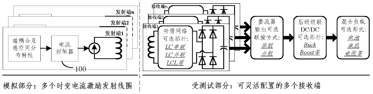
[0054] See figure 1 Explain that a static simulation system for dynamic wireless power supply described i...


PUM


Abstract

The invention discloses a static simulation system for dynamic wireless charging, and belongs to the field of wireless electric energy transmission. The problem that an existing wireless power supplystatic simulation method is not flexible enough in receiving end configuration, and insufficient in simulation capacity for extremely high driving speed is solved. The system comprises a current controller, n transmitting ends and n receiving ends; the n transmitting ends and the n receiving ends are corresponding one by one to form n pairs of combinations; the transmitting end and the receiving end in each pair combination are relatively static; a transmitting coil of the transmitting end in each pair of combination is magnetically coupled with a receiving coil of the corresponding receivingend, so that the receiving end in each pair of combination can obtain time-varying induced voltage for simulating a real driving fluctuation rule; the magnetic coupling mutual-inductance coefficient in each pair of combination is fixed; the current controller controls the n transmitting ends in an open-loop control way according to the distribution characteristics of magnetic coupling mutual-inductance space between the transmitting end and the receiving end in each pair of combination, so that the transmitting coils in the n transmitting ends can produce time-variable current excitation sources. The system is mainly used for wireless power supply tests.

Description

Technical field [0001] The invention belongs to the field of wireless power transmission. Background technique [0002] Dynamic wireless power supply technology can realize battery supplementation or direct drive power supply during electric vehicle driving, and it has a very positive effect on improving the cruising range and energy utilization efficiency of electric vehicles. In order to complete the test of the system, it is necessary to build a dedicated dynamic test platform. This platform generally needs to build the relative movement between the transmitting and receiving structure to create dynamic driving characteristics. However, this traditional test method has relatively large problems in two aspects. The first problem is that it is difficult to implement a wide speed range driving test. Second, the relative movement of the transmitting and receiving structures will lead to poor adaptability of the test, because the test of different receiving end structure configurat...

Claims


Application Information

Patent Timeline
Patent Type & Authority Applications(China)
IPC IPC(8): H02J50/10B60L53/12
CPCY02T10/72Y02T10/7072Y02T10/70Y02T90/14
Inventor 张千帆宋双成董帅崔超唐佳棋何志浩
Owner HARBIN INST OF TECH
Why Eureka
Try Eureka