Sealing water cooling structure for motor shell

A motor casing and water-cooling technology, which is applied in the direction of the casing/cover/support, electrical components, electromechanical devices, etc., can solve the problems of complex structure of the outer water jacket, easy damage of the sealing ring, and difficult casting, so as to prevent The effect of motor leakage failure, ensuring sealing reliability and improving heat dissipation efficiency

Pending Publication Date: 2019-06-11
CHONGQING TSINGSHAN IND
View PDF0 Cites 4 Cited by
  • Summary
  • Abstract
  • Description
  • Claims
  • Application Information

AI Technical Summary

Problems solved by technology

[0002] At present, in the existing water-cooled sealing structure of the motor casing, the outer water jacket and the inner water jacket are formed by casting respectively. Since the main structure of the water channel is integrated on the inner water jacket, the outer water jacket is fixed on the motor casing. , the structure is very complex, especially in the all-in-one powertrain products, the structure of the outer water jacket is more complicated. Therefore, under the condition that different OEMs have different requirements for the peripheral envelope of the same platform product, it is necessary to redesign the outer water jacket. It becomes very difficult, which makes the adaptability of the product poor and brings huge mold opening costs, and the mold is too complicated and casting is difficult
In addition, sealing rings are usually used for waterway sealing in the sealing structure. This sealing method is prone to problems such as aging and failure of the sealing rings, easy damage of the sealing rings during installation, and poor integrity of the inner and outer water jackets.

Method used


Image

  • Sealing water cooling structure for motor shell
  • Sealing water cooling structure for motor shell
  • Sealing water cooling structure for motor shell

Examples


Embodiment Construction

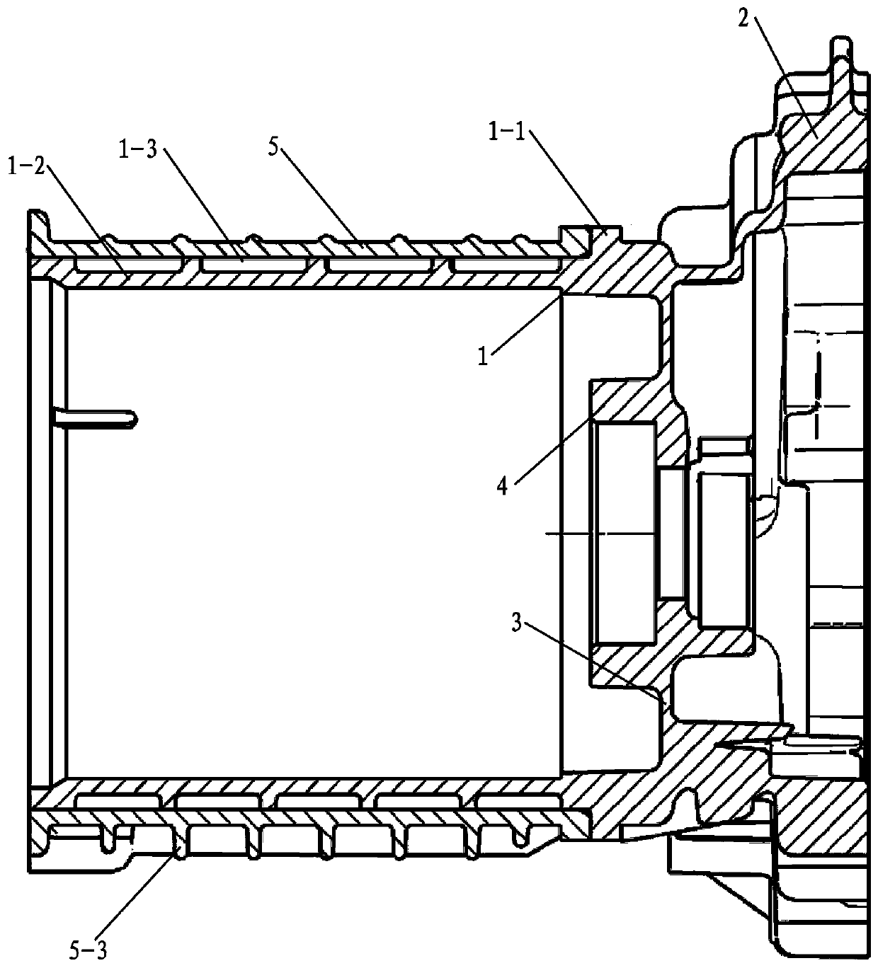
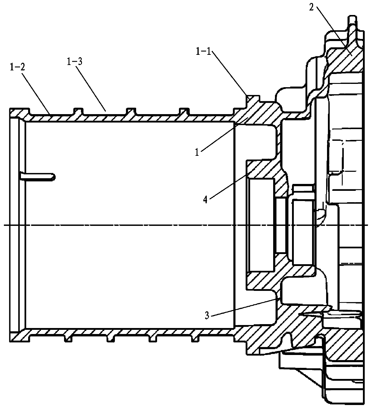
[0015] see Figure 1 to Figure 3 , a motor housing sealed water-cooled structure, including an integrally formed housing with a reducer case part 2 and a motor case part 1, and a partition wall provided between the motor case part 1 and the reducer case part 2 3, the partition wall 3 is provided with a motor front bearing seat 4, so that the reducer and the motor share one end face, which can not only reduce the axial length of the system assembly, make the internal structure of the system more compact, but also improve the system NVH performance. One end of the motor box part 1 adjacent to the reducer box part 2 is provided with an outwardly protruding positioning flange 1-1, and the positioning flange 1-1 is separated from the circumference of the motor box part 1 at the mouth end of the motor box part 1. The outer wall section is the waterway setting part 1-2, the outer surface of the waterway setting part 1-2 is provided with a spiral waterway groove 1-3 around the circum...


PUM


Abstract

The invention relates to a sealing water cooling structure for a motor shell, which comprises an integrally formed shell with a speed reducer box part and a motor box part. The motor box part is separated from the speed reducer box part by an arranged separation wall; a motor front bearing seat is arranged on the separation wall; a positioning flange protruding outwards is formed at one end of themotor box part, which is adjacent to the speed reducer box part; a part between the positioning flange and a motor box part circumference outer wall section of a motor box part port end is a waterwaydisposing part; a spiral waterway groove surrounding the circumference is formed on the outer surface of the waterway disposing part; a waterway sealing jacket sleeves the waterway disposing part inan interference fit mode; one end of the waterway sealing jacket is positioned by the positioning flange; a matching seam of the waterway sealing jacket and the positioning flange is sealed by welding, and a matching seam of the other end of the waterway sealing jacket and the waterway disposing part port end is sealed by welding, so that the spiral waterway groove forms a closed cooling waterway;a water inlet and a water outlet are respectively formed on the side wall of the waterway sealing jacket; and a plurality of heat dissipation ribs are arranged on the outer wall surface of the waterway sealing jacket.

Description

technical field [0001] The invention relates to a water cooling structure, in particular to a water cooling sealing structure of a motor casing. Background technique [0002] At present, in the existing water-cooled sealing structure of the motor casing, the outer water jacket and the inner water jacket are formed by casting respectively. Since the main structure of the water channel is integrated on the inner water jacket, the outer water jacket is fixed on the motor casing. , the structure is very complex, especially in the all-in-one powertrain products, the structure of the outer water jacket is more complicated. Therefore, under the condition that different OEMs have different requirements for the peripheral envelope of the same platform product, it is necessary to redesign the outer water jacket. It becomes very difficult, which makes the adaptability of the product poor, which brings huge mold opening costs, and the mold is too complicated, which makes casting difficu...

Claims


Application Information

Patent Timeline
Patent Type & Authority Applications(China)
IPC IPC(8): H02K5/20
Inventor 马金金侯淼吴守国周月发张宇林龙谭智徐迪曾智
Owner CHONGQING TSINGSHAN IND
Why Eureka
Try Eureka