A moisture-proof remote electronic monitoring device

An electronic monitoring and remote technology, which is applied in the direction of TV, color TV, electrical components, etc., can solve the problems of shortening the service life of the device, not having moisture-proof function, and moisture damage of the device, so as to prolong the service life, occupy a small space, improve The effect of moisture resistance

Inactive Publication Date: 2020-09-29
CHONGQING COLLEGE OF ELECTRONICS ENG
View PDF7 Cites 0 Cited by
  • Summary
  • Abstract
  • Description
  • Claims
  • Application Information

AI Technical Summary

Problems solved by technology

[0004] Some existing remote electronic monitoring devices do not have a moisture-proof function. Moisture can greatly damage electronic products. If there is no moisture-proof function, the service life of the device will be shortened. Some devices are not designed to be sealed enough, which will also cause some moisture to enter the device, resulting in Device exposed to moisture

Method used


Image

  • A moisture-proof remote electronic monitoring device
  • A moisture-proof remote electronic monitoring device
  • A moisture-proof remote electronic monitoring device

Examples


no. 1 example

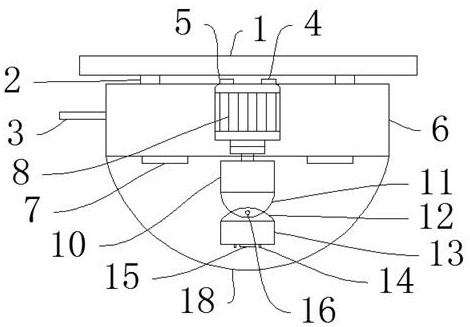
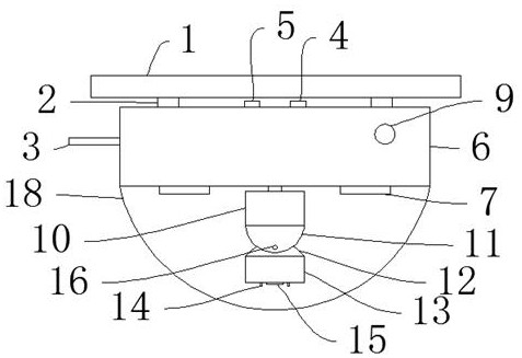
[0037] Such as Figure 1-Figure 7 As shown, a moisture-proof remote electronic monitoring device of the present invention includes a suspension plate 1, a buckle 2, a protective shell 6, a monitoring circuit board 10, a transparent cover 18, and a buckle 2 and a buckle 2 are arranged above the protective shell 6. It is used to connect with the protective shell 6. There is a hanging plate 1 above the buckle 2. The hanging plate 1 is used to install the rear support device. There is a miniature signal interface terminal 5 between the buckles 2. Equipment and output receiving signals, the side of the micro-signal interface terminal 5 is provided with a power interface 4, the power interface 4 is used to provide electric energy for the device after being connected to the power supply, the power interface 4 is used to provide electric energy for the device after being connected to the power supply, and the protective shell 6 is provided inside There is a first servo motor 8, a wire...

no. 2 example

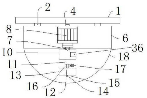
[0039] The difference between the second embodiment and the first embodiment is that the suspension plate 1 is connected to the buckle 2 by screws, and the buckle 2 is connected to the protective shell 6 . Specifically, the suspension plate 1 and the buckle 2 are connected by screws. The screw connection can ensure the reliable connection between the connectors. The screw connection has high installation efficiency. fast and convenient. In the present invention, the sliding groove 34 is formed on the first installation box 30 and the second installation box 31 , and the sliding plate 35 is slidably connected in the sliding groove 34 . So set, slide plate 35 is opened during installation, easy to install, closes during use, makes it dust-proof and moisture-proof.

no. 3 example

[0041] The difference between the third embodiment and the first embodiment is that the first servo motor 8 is connected to the monitoring circuit board 10 by bolts, and the monitoring circuit board 10 is connected to the fixing block 11 by screws. Specifically, the first servo motor 8 and the monitoring circuit board 10 are connected by bolts. The bolt connection structure is simple, quick to manufacture and install, and convenient to disassemble, which is beneficial to later maintenance. The monitoring circuit board 10 and the fixed block 11 are connected by screws. The screw connection can Ensure reliable connection between connectors.

[0042] Working principle: when the device is in use, install the suspension plate 1 on the wall, clamp the protective case 6 on the buckle 2, connect the power interface 4 to the power supply, press the switch 9, the switch 9 powers up the device, and the camera 13 will The picture captured by the lens 15 is output to the monitoring circuit...


PUM


Abstract

The invention discloses a moisture-proof remote electronic monitoring device, which comprises a hanging pan, a buckle, a protective case, a monitoring circuit board, and a transparent cover. The suspension plate, the micro-signal interface terminal is provided between the buckles, the power interface is provided on the side of the micro-signal interface terminal, the first servo motor is provided inside the protective case, and the wireless signal is provided on the side of the protective case. Rod, the front part of the protective case is provided with a switch, the transparent cover is provided under the protective case, a heating strip is provided on the protective case, the protective case and the heating strip are connected by screws, and the first The monitoring circuit board is arranged under a servo motor. The advantages are: the present invention has an active moisture-proof function, heating and dehumidification, prolonging the service life of the device, and the device is designed in a sealed state to prevent moisture from entering the device, further preventing moisture.

Description

technical field [0001] The invention relates to the field of remote electronic monitoring, in particular to a moisture-proof remote electronic monitoring device. Background technique [0002] A typical TV monitoring system is mainly composed of five parts: front-end monitoring equipment, transmission equipment, back-end storage, control and display equipment. The back-end equipment can be further divided into central control equipment and sub-control equipment. The connection between them (also known as the transmission system) can be realized by various methods such as cables, optical fibers, and microwaves. [0003] The video surveillance system has developed in just over 20 years, from analog surveillance to fiery digital surveillance and then to the ascendant network video surveillance in 2012. Earth-shaking changes have taken place. Now that IP technology is gradually unifying the world, it is necessary for us to re-understand the video surveillance system. Development...

Claims


Application Information

Patent Timeline
Patent Type & Authority Patents(China)
IPC IPC(8): H04N5/225H04N5/232H04N5/235H04N7/18G08C17/02G03B17/55G03B17/08
Inventor 陈宗梅
Owner CHONGQING COLLEGE OF ELECTRONICS ENG
Why Eureka
Try Eureka