A moisture-proof remote electronic monitoring device
An electronic monitoring and remote technology, which is applied in the direction of TV, color TV, electrical components, etc., can solve the problems of shortening the service life of the device, not having moisture-proof function, and damage to electronic products, so as to prolong the service life, occupy a small space, and improve The effect of moisture resistance
- Summary
- Abstract
- Description
- Claims
- Application Information
AI Technical Summary
Problems solved by technology
Method used
Image
Examples
no. 1 example
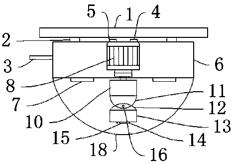
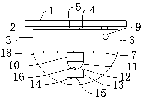
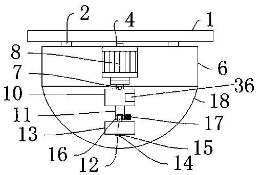
[0037] Such as Figure 1-Figure 7 As shown, a moisture-proof remote electronic monitoring device of the present invention includes a suspension plate 1, a buckle 2, a protective shell 6, a monitoring circuit board 10, a transparent cover 18, and a buckle 2 and a buckle 2 are arranged above the protective shell 6. It is used to connect with the protective shell 6. There is a hanging plate 1 above the buckle 2. The hanging plate 1 is used to install the rear support device. There is a miniature signal interface terminal 5 between the buckles 2. Equipment and output receiving signals, the side of the micro-signal interface terminal 5 is provided with a power interface 4, the power interface 4 is used to provide electric energy for the device after being connected to the power supply, the power interface 4 is used to provide electric energy for the device after being connected to the power supply, and the protective shell 6 is provided inside There is a first servo motor 8, a wire...
no. 2 example
[0039] The difference between the second embodiment and the first embodiment is that the suspension plate 1 is connected to the buckle 2 by screws, and the buckle 2 is connected to the protective shell 6 . Specifically, the suspension plate 1 and the buckle 2 are connected by screws. The screw connection can ensure the reliable connection between the connectors. The screw connection has high installation efficiency. fast and convenient. In the present invention, the sliding groove 34 is formed on the first installation box 30 and the second installation box 31 , and the sliding plate 35 is slidably connected in the sliding groove 34 . So set, slide plate 35 is opened during installation, easy to install, closes during use, makes it dust-proof and moisture-proof.
no. 3 example
[0041] The difference between the third embodiment and the first embodiment is that the first servo motor 8 is connected to the monitoring circuit board 10 by bolts, and the monitoring circuit board 10 is connected to the fixing block 11 by screws. Specifically, the first servo motor 8 and the monitoring circuit board 10 are connected by bolts. The bolt connection structure is simple, quick to manufacture and install, and convenient to disassemble, which is beneficial to later maintenance. The monitoring circuit board 10 and the fixed block 11 are connected by screws. The screw connection can Ensure reliable connection between connectors.
[0042] Working principle: when the device is in use, install the suspension plate 1 on the wall, clamp the protective case 6 on the buckle 2, connect the power interface 4 to the power supply, press the switch 9, the switch 9 powers up the device, and the camera 13 will The picture captured by the lens 15 is output to the monitoring circuit...
PUM
 Abstract
Description
Claims
Application Information
 - R&D
- Intellectual Property
- Life Sciences
- Materials
- Tech Scout
- Unparalleled Data Quality
- Higher Quality Content
- 60% Fewer Hallucinations
Browse by: Latest US Patents, China's latest patents, Technical Efficacy Thesaurus, Application Domain, Technology Topic, Popular Technical Reports.
© 2025 PatSnap. All rights reserved.Legal|Privacy policy|Modern Slavery Act Transparency Statement|Sitemap|About US| Contact US: help@patsnap.com


