
Communication equipment and optical module with heat dissipation structure

A technology of heat dissipation structure and communication equipment, applied in the field of optical modules, can solve the problems of the optical module not working properly, the volume heat density is increased, the chip performance is reduced, etc., and achieves the effect of a compact thermal conductive structure, a small number of parts, and easy assembly.

Pending Publication Date: 2019-06-11
LINKTEL TECH CO LTD
View PDF5 Cites 5 Cited by
  • Summary
  • Abstract
  • Description
  • Claims
  • Application Information

AI Technical Summary

Problems solved by technology

At the same time, the power of the optical module continues to increase, and the thermal density of the volume continues to increase, resulting in a high temperature when the optical module is working. The performance of the temperature-sensitive electro-optic / photoelectric conversion components and chips in the optical module will be greatly reduced, and even lead to the entire optical module. not working or failing

Method used


Image

  • Communication equipment and optical module with heat dissipation structure
  • Communication equipment and optical module with heat dissipation structure
  • Communication equipment and optical module with heat dissipation structure

Examples


Embodiment Construction

[0024] The following will clearly and completely describe the technical solutions in the embodiments of the present invention with reference to the accompanying drawings in the embodiments of the present invention. Obviously, the described embodiments are only some, not all, embodiments of the present invention. Based on the embodiments of the present invention, all other embodiments obtained by persons of ordinary skill in the art without making creative efforts belong to the protection scope of the present invention.

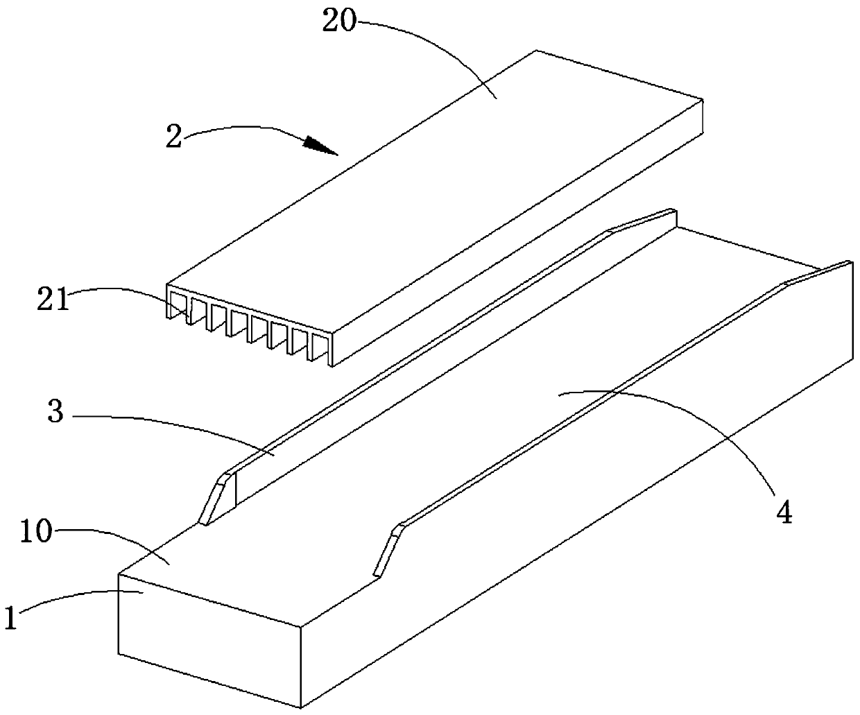
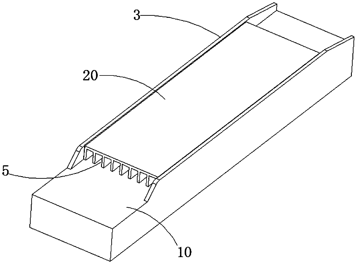
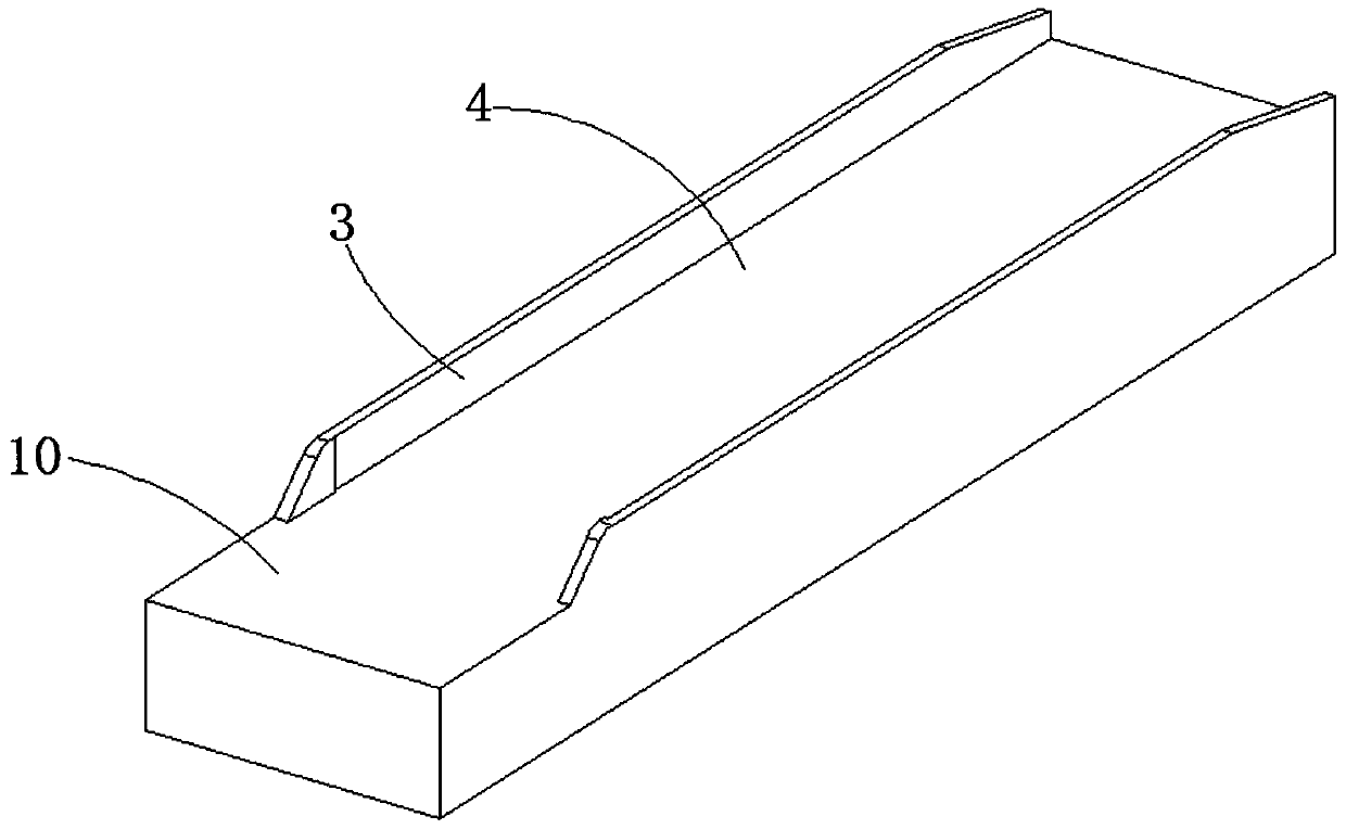
[0025] see Figure 1-5 , an embodiment of the present invention provides an optical module with a heat dissipation structure, including an optical module body 1 and a heat conduction structure 2 disposed on at least one outer surface 10 of the optical module body 1, and the heat conduction structure 2 includes several The first baffle plate 21 and the base plate 20 for each of the first baffle plates 21 are installed. Between the outer surfaces 10 , and an en...


PUM


Abstract

The invention relates to the technical field of optical modules, and provides an optical module with a heat dissipation structure. The optical module comprises an optical module body, and further comprises a heat conduction structure arranged on the outer surface of at least one side of the optical module body, wherein the heat conduction structure comprises a plurality of first baffles and a bottom plate for mounting the first baffles; the bottom plate and the outer surface are oppositely arranged; each first baffle is located between the bottom plate and the outer surface; and one end, far away from the bottom plate, of each first baffle is in contact with the outer surface. The invention further provides communication equipment, wherein the communication equipment comprises a communication equipment body and the optical module. According to the optical module with the heat dissipation structure provided by the invention, heat transmitted to the outer surface of the optical module body is conducted through the heat conduction structure, and the heat dissipation area is enlarged through the bottom plate and the plurality of baffles, so that the heat dissipation effect is improved;and in addition, the baffles are arranged between the bottom plate and the outer surface, and the formed openings in the two ends can form air convection, so that the heat dissipation speed can be accelerated, and electromagnetic leakage can be effectively controlled.

Description

technical field [0001] The invention relates to the technical field of optical modules, in particular to a communication device and an optical module with a heat dissipation structure thereof. Background technique [0002] The development trend of high integration and high speed of optical communication modules makes optical modules continue to develop in the direction of multi-channel, miniaturization, and high density. At the same time, the power of the optical module continues to increase, and the thermal density of the volume continues to increase, resulting in a high temperature when the optical module is working. The performance of the temperature-sensitive electro-optic / photoelectric conversion components and chips in the optical module will be greatly reduced, and even lead to the entire optical module. Not functioning properly or failing. Contents of the invention [0003] The purpose of the present invention is to provide a communication device and its optical m...

Claims


Application Information

Patent Timeline
Patent Type & Authority Applications(China)
IPC IPC(8): H05K7/20
Inventor 彭峰李林科吴天书杨现文张健
Owner LINKTEL TECH CO LTD
Learn More