Pipeline of respiratory therapy apparatus

A breathing therapy and pipeline technology, applied in respirator and other directions, can solve problems such as limited effect of preventing condensation water, inability to effectively prevent condensation water, etc., to achieve the effect of preventing the generation of condensation water and realizing the transmission of information

Pending Publication Date: 2019-06-14
广州鲸科医疗科技有限公司
View PDF0 Cites 4 Cited by
  • Summary
  • Abstract
  • Description
  • Claims
  • Application Information

AI Technical Summary

Problems solved by technology

However, these two single-layer heated breathing tubes on the market have limited effect on preven

Method used


Image

  • Pipeline of respiratory therapy apparatus
  • Pipeline of respiratory therapy apparatus
  • Pipeline of respiratory therapy apparatus

Examples


Embodiment Construction

[0019] The specific implementation manners of the present invention will be further described in detail below in conjunction with the accompanying drawings and embodiments. The following examples are used to illustrate the present invention, but are not intended to limit the scope of the present invention.

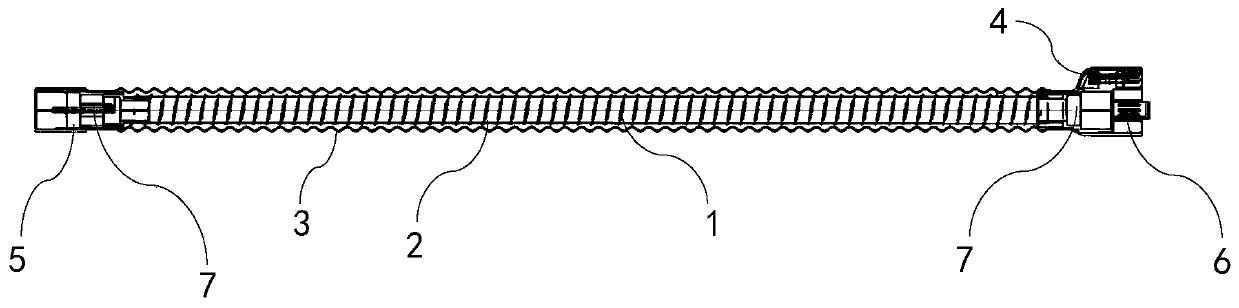
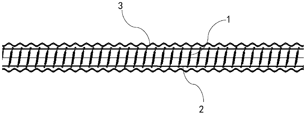
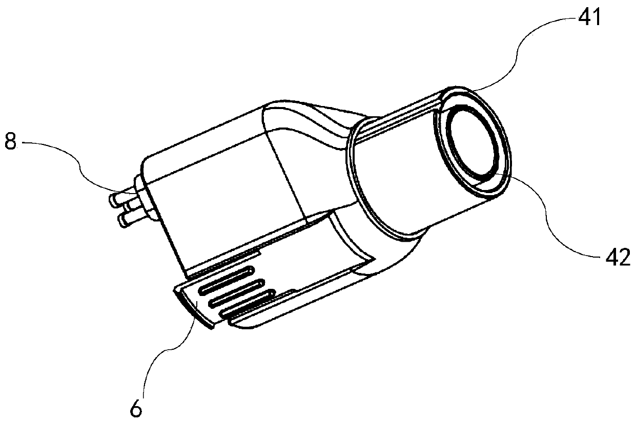
[0020] Please refer to the attached Figure 1-4 , a pipeline of a respiratory therapeutic apparatus provided by the present invention, which includes a pipeline body and a heating wire 1 arranged in the pipeline body, the pipeline body includes a first pipeline 2 and a heating wire 1 sleeved in the pipeline body. The second pipeline 3 outside the first pipeline 2, the heating wire 1 is arranged between the first pipeline 2 and the second pipeline 3, from one end to the other end of the pipeline body Wound in a helical shape; it also includes a first joint 4 for connecting the machine end and a second joint 5 for the patient end arranged at both ends of the pipeline body; ...


PUM


Abstract

The invention discloses a pipeline of a respiratory therapy apparatus. The pipeline comprises a pipeline body and a heating wire arranged in the pipeline body. The pipeline body comprises a first pipeline and a second pipeline sleeving the first pipeline, the heating wire is arranged between the first pipeline and the second pipeline, and the heating wire is wound spirally from one end to the other end of the pipeline body. The pipeline further comprises a first joint for connecting the machine end and a second joint for the patient end which are arranged at two ends of the pipeline body; thefirst joint or/and the second joint are provided with a temperature sensor; one side of the first joint is provided with an electrical connection portion extending from below, and the electrical connection portion is provided with a plurality of contacts. The contacts include contacts connected with the heating wire and the temperature sensor through electric signals. The pipeline of the respiratory therapy apparatus can more effectively prevent or reduce the generation of condensed water while achieving warming.

Description

technical field [0001] The invention relates to a pipeline of a respiratory therapeutic apparatus. Background technique [0002] On the one hand, the heating of the breathing tube can heat up or keep warm the gas flowing through the tube. On the other hand, the more important purpose is to solve or alleviate the problem of condensed water generated on the tube wall by the heated and humidified air flowing through the tube. At present, there are two main types of heated breathing circuits on the market, both of which are single-layer. One is an ordinary bellows, and a spiral heating wire is arranged in the cavity of the pipeline; the other is that the heating wire is integrated with the pipeline, and the heating wire is fixedly attached to the pipe wall. However, these two single-layer heated breathing tubes on the market have limited effect on preventing condensation water, and cannot effectively prevent condensation water generation under the condition of low room temperat...

Claims


Application Information

Patent Timeline
IPC IPC(8): A61M16/00A61M16/10A61M16/16A61M16/08
Inventor 李翔宇何令文
Owner 广州鲸科医疗科技有限公司
Why Eureka
Try Eureka