
Anti-collision unmanned aerial vehicle

A drone and anti-collision technology, applied in the field of drones, can solve the problem of force on the rotor arm, and achieve the effect of protecting it from damage

Inactive Publication Date: 2019-06-14
XIAN DINGZI ELECTRONICS INFORMATION SCI & TECH
View PDF0 Cites 0 Cited by
  • Summary
  • Abstract
  • Description
  • Claims
  • Application Information

AI Technical Summary

Problems solved by technology

[0006] In order to solve the technical problem that the entire rotor arm will be stressed when the rigidly connected protective structure in the prior art collides, the present invention provides the following technical solutions:

Method used


Image

  • Anti-collision unmanned aerial vehicle
  • Anti-collision unmanned aerial vehicle
  • Anti-collision unmanned aerial vehicle

Examples


Embodiment 1

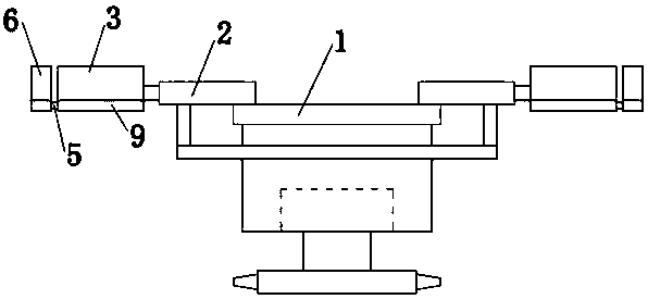
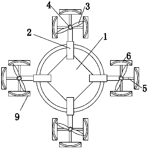
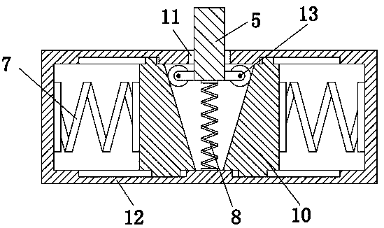
[0027] In order to solve the technical problem that in the prior art, when the rigidly connected protective structure collides, the entire rotor arm will be stressed, so it is easy to cause the UAV to fall and damage the technical problem. This embodiment provides an anti-collision UAV. Such as figure 1 , figure 2 As shown, including the rotor platform 1, the rotor platform 1 is evenly distributed with rotor arms 2, and the rotor arm 2 end is provided with a rotor 3, and the rotor 3 is driven to rotate by the flight motor 4, wherein each end of the rotor arm 2 is provided with an anti-collision mechanism; the anti-collision mechanism includes a connecting arm 5 fixed at the end of the rotor arm, the end of the connecting arm 5 is inserted into a shock absorbing assembly 9, the top surface of the shock absorbing assembly 9 is provided with an anti-collision plate 6, and the anti-collision plate 6 is an arc-shaped structure , whose center coincides with the center of rotation ...

Embodiment 2

[0031] On the basis of the foregoing embodiments, each anti-collision mechanism is provided with three anti-collision plates 6 and connecting arms 5, and the three connecting arms 5 and the rotor arm 2 are arranged in a cross shape; the three connecting arms 5 are connected with each other by screws. The rotor arm 2 is fixedly connected.

[0032] The central angle of the above-mentioned anti-collision plate 6 is set to 60°-90°, and the number is three, and each connecting arm 5 is fixedly connected with the arc center of the anti-collision plate 6, so two adjacent anti-collision plates The maximum gap angle between the collision plates 6 is 30°, the minimum is 0, and the anti-collision plate 6 is not provided at the rotor arm 2 because when the drone is flying, only the outer side will collide, and the inner side is the rotor arm 2. place will not collide with the obstacle, so the anti-collision plate 6 is not provided here, and when the angle between the two anti-collision pl...


PUM


Abstract

The invention relates to an anti-collision unmanned aerial vehicle that comprises a rotor wing platform; rotor wing arms are evenly distributed on the edge of the rotor wing platform; rotor wings arearranged at the tail ends of the rotor wing arms, and are driven by a flight motor to rotate; an anti-collision mechanism is arranged at the tail end of each rotor wing arm; the anti-collision mechanism comprises a connecting arm fixed to the tail end of the rotor wing arm; an anti-collision plate is arranged at the tail end of the connecting arm and is of an arc structure, and the circle center of the anti-collision plate coincides with the rotation center of the rotor wing. According to the unmanned aerial vehicle, the anti-collision plate and the rotor wing arm are elastically connected; when the unmanned aerial vehicle touches an obstacle, a buffering can be achieved; the rotor wing arm cannot be stressed, and therefore the rotor wings and the rotor wing arms are protected against damages.

Description

technical field [0001] The invention belongs to the technical field of unmanned aerial vehicles, and in particular relates to an anti-collision unmanned aerial vehicle. Background technique [0002] Unmanned aircraft, referred to as UAV, is a new concept equipment in rapid development, which has the advantages of flexible maneuvering, quick response, unmanned flight, and low operation requirements. At present, UAVs have been widely used in the three major fields of military, scientific research, and civilian use, especially in the fields of electric power, communication, meteorology, agriculture, ocean, exploration, photography, patrol, anti-terrorism and explosives disposal. [0003] Since drones need to fly in different environments, the possibility of damage is very high, especially if the rotor part is damaged a little, it will cause imbalance and cause the drone to fall and be damaged. Therefore, in order to solve this problem, prevent Crashing drones has entered every...

Claims


Application Information

Patent Timeline
Patent Type & Authority Applications(China)
IPC IPC(8): B64C27/32B64D45/00
Inventor 盖勇
Owner XIAN DINGZI ELECTRONICS INFORMATION SCI & TECH
Learn More