
Hinging device for heavy loads

A hinged, bearing surface technology, used in pivot connection, transportation and packaging, load hanging components, etc., can solve the problems of time-consuming and laborious installation, weakening the weight of related components, and heavy structure, so as to facilitate installation and save resource costs. , the effect of simple connection

Active Publication Date: 2019-06-28
HUNAN CHANGZHONG MACHINERY
View PDF7 Cites 0 Cited by
  • Summary
  • Abstract
  • Description
  • Claims
  • Application Information

AI Technical Summary

Problems solved by technology

[0006] The invention provides a heavy-duty hinged device to solve the technical problems of the existing hinged device, such as bulky structure, weakened bearing weight of related components, time-consuming and labor-intensive installation, etc.

Method used


Image

  • Hinging device for heavy loads
  • Hinging device for heavy loads
  • Hinging device for heavy loads

Examples


Embodiment 1

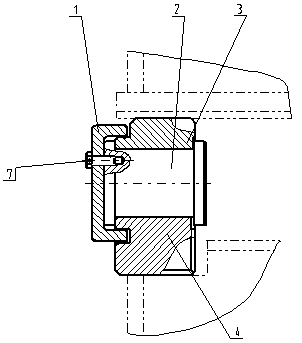
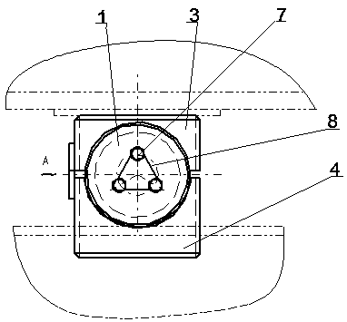
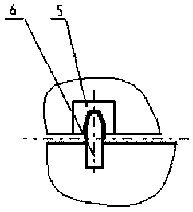
[0037] Such as figure 1 , figure 2 , image 3 , Figure 5 , Figure 6 As shown, a hinged device for heavy load is composed of a pin shaft (2), an upper semicircular block (3), a lower semicircular block (4), a circular cover plate (1) and a rotation degree of freedom restriction system. The above-mentioned upper semicircular block (3) is placed above the pin shaft (2), the lower semicircular block (4) is placed under the pin shaft (2), and the inner side of the circular cover plate (1) is connected with the upper semicircular block (3) at the same time. ) and one end of the lower semicircle block (4).

[0038] The circular cover plate (1) and the pin shaft (2) are connected by 3 or 5 sets of screws (7), and the screws (7) are connected and reinforced by steel wires (8).

[0039] The screws (7) are located at 1 / 3 of the radius from the center of the circular cover (1) to the circumference, that is to say, 3 or 5 sets of screws (7) are located at the center of the circle w...

Embodiment 2

[0051] Such as figure 1 , figure 2 , Figure 4 , Figure 5 , Figure 6 As shown, a hinged device for heavy load is composed of a pin shaft (2), an upper semicircular block (3), a lower semicircular block (4), a circular cover plate (1) and a rotation degree of freedom restriction system. The above-mentioned upper semicircular block (3) is placed above the pin shaft (2), the lower semicircular block (4) is placed under the pin shaft (2), and the inner side of the circular cover plate (1) is connected with the upper semicircular block (3) at the same time. ) and one end of the lower semicircle block (4).

[0052] The circular cover plate (1) and the pin shaft (2) are connected by 3 or 5 sets of screws (7), and the screws (7) are connected and reinforced by steel wires (8).

[0053] The screws (7) are located at 1 / 3 of the radius from the center of the circular cover (1) to the circumference, that is to say, 3 or 5 sets of screws (7) are located at the center of the circle ...


PUM


Abstract

The invention relates to a hinging device for heavy loads. The hinging device is composed of a pin shaft, an upper semicircular block, a lower semicircular block, a round cover plate and a rotating freedom degree limiting system. The upper semicircular block is arranged on the pin shaft. The lower semicircular block is arranged under the pin shaft. The inner side of the round cover plate is connected with one end of the upper semicircular block and one end of the lower semicircular block at the same time. One or more sets of wedge blocks are welded to the side face of the upper semicircular block. One or more sets of wedge pins are welded to the lower semicircular block. The wedge blocks and the wedge pins are in clearance fitting, and it can be ensured that an upper part and a lower parthave small rotating freedom degrees. When the relative rotating angle between the upper semicircular block and the lower semicircular block is larger than a set value, the rotating freedom degree limiting system rotates to control equipment to be shut down automatically. The hinging device is compact in structure, simple in connecting manner, convenient to install, and capable of bearing the larger weight, and keeps the small rotating freedom degrees, and by means of intelligent control, the situation that due to unevenness of the track or rail gnawing, impact force of the upper part and the lower part causes potential safety hazards to equipment can be avoided.

Description

technical field [0001] A heavy-duty hinge device belongs to the technical field of mechanical connection, and in particular relates to a connection between heavy-duty mechanisms. Background technique [0002] Articulated joints and bolted joints are widely used in various fields, especially in the mechanical field. The bolted connection is a fixed connection, and the two connected parts have no degree of freedom and cannot move. The hinged connection device can make the two connected parts rotate around the hinge due to the release of one or more rotational degrees of freedom. Therefore, hinged devices are widely used in places where rotary motion is required. [0003] Stacker-reclaimers and excavators are heavy machinery with a wide range of applications. The traditional method of these equipment is that the traveling mechanism and the portal frame are connected by bolts. Due to the influence of manufacturing, installation accuracy and equipment deformation during use, it...

Claims


Application Information

Patent Timeline
Patent Type & Authority Applications(China)
IPC IPC(8): F16C11/04B66C9/16
Inventor 许鹏万正喜颜晓磊
Owner HUNAN CHANGZHONG MACHINERY
Learn More