Spray gun assembly and spraying robot

A technology for spraying robots and components, which is applied to cleaning machinery, construction, and carpet cleaning, etc. It can solve problems such as inability to rotate, move up and down in the longitudinal direction, and move left and right in the horizontal direction, so as to reduce potential safety hazards, ensure installation, and reduce differences. Effect

Inactive Publication Date: 2019-06-14
GUANGDONG BOZHILIN ROBOT CO LTD
View PDF6 Cites 8 Cited by
  • Summary
  • Abstract
  • Description
  • Claims
  • Application Information

AI Technical Summary

Problems solved by technology

However, at present, the spraying process of buildings is still done manually, and this construction method will be restricted by the natural environment, and at the same time, the quality of spraying cannot be guaranteed. In addition, this method cannot ensure the safety of workers.
In order to solve this problem, there is a spraying robot that can automatically spray the exterior wall or interior wall. However, when the current spraying robot is spraying, the spray gun itself has a low degree of freedom and cannot move left and right in the horizontal direction. The direction moves up and down and cannot be rotated, which makes the spraying robot need to move frequently when spraying, which will lead to slow spraying efficiency and inconvenient spraying

Method used


Image

  • Spray gun assembly and spraying robot
  • Spray gun assembly and spraying robot
  • Spray gun assembly and spraying robot

Examples


Embodiment Construction

[0101] In order to understand the above-mentioned purpose, features and advantages of the present invention more clearly, the present invention will be further described in detail below in conjunction with the accompanying drawings and specific embodiments. It should be noted that, in the case of no conflict, the embodiments of the present application and the features in the embodiments can be combined with each other.

[0102] In the following description, many specific details are set forth in order to fully understand the present invention. However, the present invention can also be implemented in other ways than described here. Therefore, the protection scope of the present invention is not limited by the specific implementation disclosed below. Example limitations.

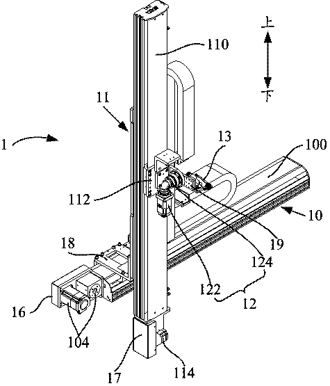
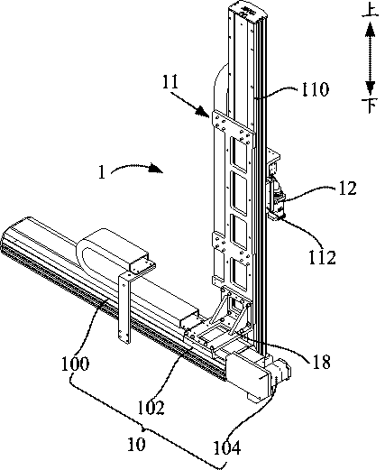
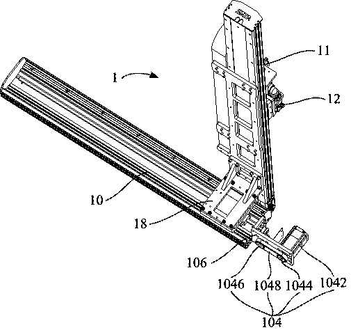
[0103] Refer below Figure 1 to Figure 13 The spray gun assembly 1 and the spraying robot provided according to the embodiments of the present invention will be described.

[0104] Such as Figure 1 to Fig...


PUM


Abstract

The invention provides a spray gun assembly and a spraying robot. The spray gun assembly comprises a first guide rail assembly, a second guide rail assembly, a rotating driving part, and a spray gun,wherein the first guide rail assembly comprises a first guide rail mounted on a frame body, a first slide block slidably mounted on the first guide rail and a first slide driving part for driving thefirst slide block to slide, and the first guide rail is arranged in the transverse direction of the working surface; the second guide rail assembly comprises a second guide rail, a second slide block,and a second slide driving part, wherein the second guide rail is mounted on the first slide block and is arranged in the longitudinal direction of the working surface, the second slide block is slidably mounted on the second guide rail, and the second slide driving part is used for driving the second slide block to slide; the rotating driving part is mounted on the second slide block and is provided with a rotating driving shaft; the spray gun is mounted on the rotating driving shaft; and the first slide driving part and/or the second slide driving part are/is connected with the first slideblock and/or the second slide block through a belt transmission assembly. According to the spray gun assembly, slide of the first slide block and the second slide block drives the spray gun to slide in the longitudinal direction and the transverse direction of the working surface, and at the same time, the rotating driving part can drive the spray gun to rotate.

Description

technical field [0001] The invention relates to the field of spraying, more specifically, to a spray gun assembly and a spraying robot. Background technique [0002] Today, with the rapid development of the urbanization process, in order to meet people's higher and higher living needs, various high-rise buildings have emerged as the times require. In the process of building construction, wall spraying is an indispensable construction step. However, at present, the spraying process of buildings is still done manually, and this construction method will be restricted by the natural environment, and at the same time, the quality of spraying cannot be guaranteed, and the safety of operators cannot be guaranteed in addition. In order to solve this problem, there is a spraying robot that can automatically spray the exterior wall or interior wall. However, when the current spraying robot is spraying, the spray gun itself has a low degree of freedom and cannot move left and right in...

Claims


Application Information

Patent Timeline
Patent Type & Authority Applications(China)
IPC IPC(8): E04F21/08A47L11/38
Inventor 许安鹏季瑞南苗佩巫广义
Owner GUANGDONG BOZHILIN ROBOT CO LTD
Why Eureka
Try Eureka