Component mounting supporting frame for prefabricated building

A technology of prefabricated assembly and support frame, which is applied to the on-site preparation of building components, building structure, and construction, etc., can solve the problems that the tie rods are easy to occupy more space, increase the work intensity of workers, and the support strength is weak. The effect of avoiding adjustment, reducing cost and improving support strength

Inactive Publication Date: 2019-06-14
万正河
View PDF5 Cites 5 Cited by
  • Summary
  • Abstract
  • Description
  • Claims
  • Application Information

AI Technical Summary

Problems solved by technology

[0003] When the prefabricated building is assembled, it is necessary to support the components. Most of the existing support frames are supported by a supporting diagonal rod. Since there are many components that need to be supported between a floor, the diagonal rods tend to occupy more space. The site is not convenient for workers to construct. At the same time, the support method of a single diagonal tie rod has weak support strength and cannot support larger or heavier components. In addition, after the diagonal stay rod is installed, its verticality needs to be adjusted. , the current adjustment method is generally to manually rotate the anti-wire directly, or put a steel bar on the anti-wire to rotate, and this adjustment method makes the workers need to spend a lot of force to complete the adjustment work. There are many inclined stay rods, which greatly increase the working strength of the workers. For this reason, the present invention provides a component installation support frame for prefabricated buildings.

Method used


Image

  • Component mounting supporting frame for prefabricated building
  • Component mounting supporting frame for prefabricated building
  • Component mounting supporting frame for prefabricated building

Examples


Embodiment Construction

[0024] The following will clearly and completely describe the technical solutions in the embodiments of the present invention with reference to the accompanying drawings in the embodiments of the present invention. Obviously, the described embodiments are only some, not all, embodiments of the present invention. Based on the embodiments of the present invention, all other embodiments obtained by persons of ordinary skill in the art without making creative efforts belong to the protection scope of the present invention.

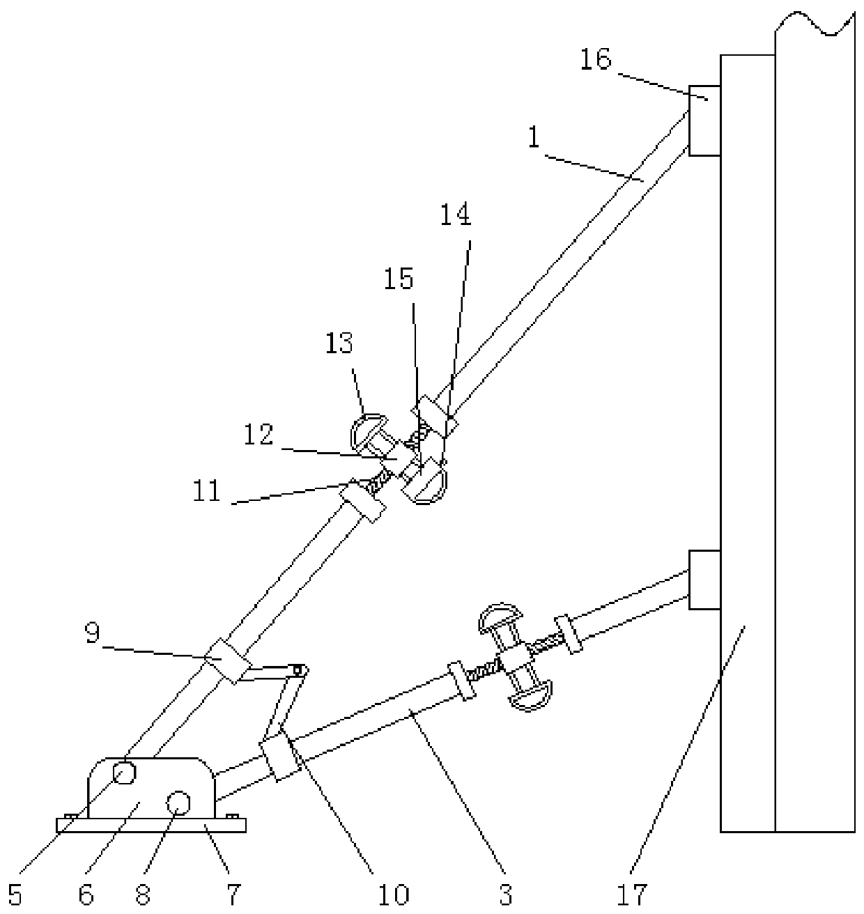
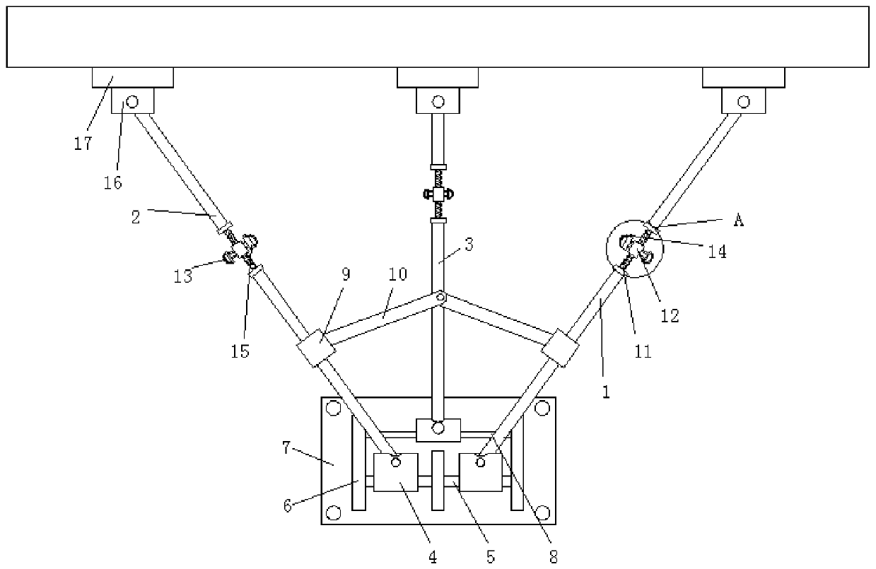
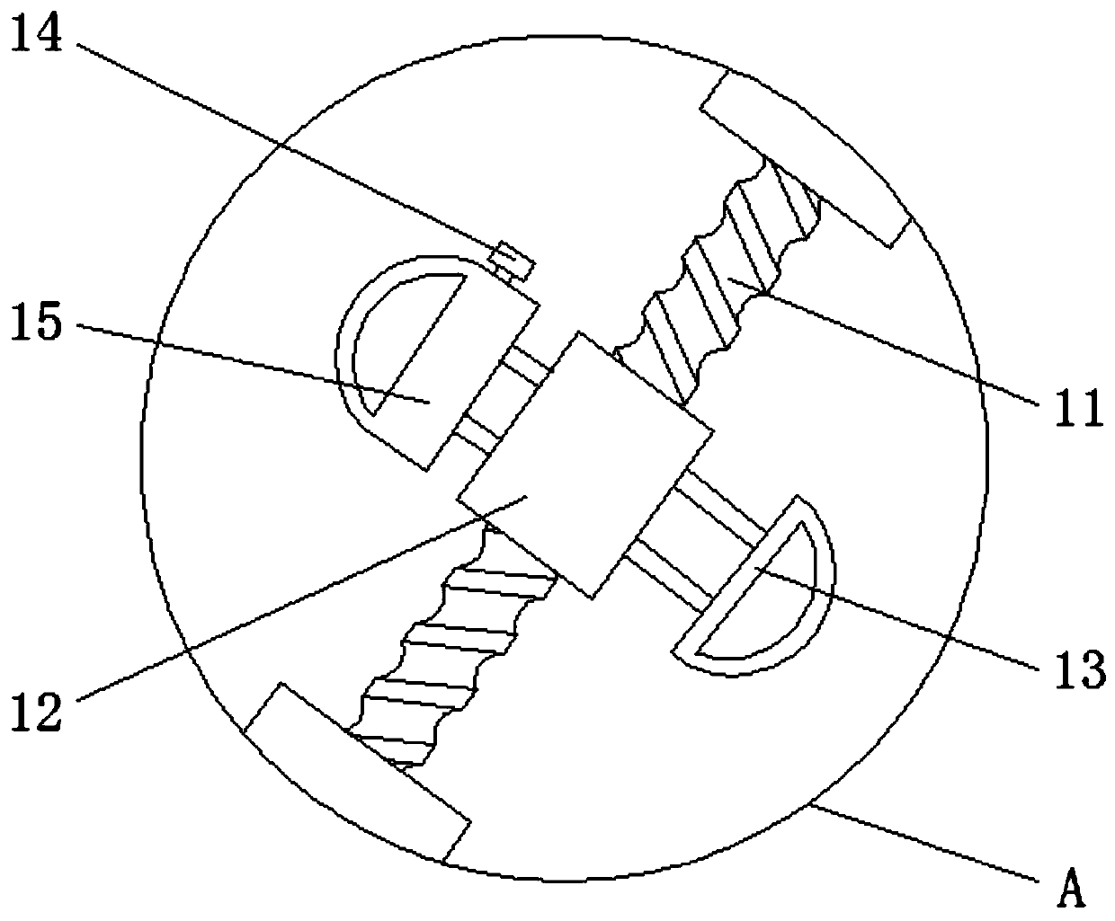
[0025] see Figure 1-5 , a component installation support frame for prefabricated buildings, including a first diagonal stay rod 1, a second diagonal stay rod 2 and a third diagonal stay rod 3, the first diagonal stay rod 1 and the second diagonal stay rod 2 and the third diagonal stay rod 3 are the same, and the first diagonal stay rod 1, the second diagonal stay rod 2 and the third diagonal stay rod 3 form a triangular support structure, and the triangular s...


PUM


Abstract

The invention relates to the technical field of prefabricated buildings, and discloses a component mounting supporting frame for prefabricated buildings. The component mounting supporting frame comprises a first inclined pull rod, a second inclined pull rod and a third inclined pull rod, wherein one end of the first inclined pull rod is hinged to one side of a mounting block; one end of the mounting block is fixedly installed outside a first movable rod; one end of the first movable rod movably sleeves one side of a bottom plate; the bottom plate is fixedly installed on a base; and one end ofthe third inclined pull rod fixedly sleeves outside of a second movable rod through the mounting block. According to the component mounting supporting frame for the prefabricated building, the supporting strength of a supporting structure is improved through a triangular supporting structure consisting of the first inclined pull rod, the second inclined pull rod and the third inclined pull rod; meanwhile, the other ends of the three inclined pull rods are integrated on one base by using the first movable rod, the second movable rod, the bottom plate and the base, so that the occupied space ofthe supporting structure is reduced; and in addition, the supporting structure can be stored conveniently through a fixing sleeve and a connecting rod.

Description

technical field [0001] The invention relates to the technical field of prefabricated buildings, in particular to a component installation support frame for prefabricated prefabricated buildings. Background technique [0002] Buildings assembled from prefabricated components on site are called prefabricated buildings. According to the form and construction method of prefabricated components, they are divided into five types: block building, plate building, box building, skeleton plate building, rising plate and rising building. types. [0003] When the prefabricated building is assembled, it is necessary to support the components. Most of the existing support frames are supported by a supporting diagonal rod. Since there are many components that need to be supported between a floor, the diagonal rods tend to occupy more space. The site is not convenient for workers to construct. At the same time, the support method of a single diagonal tie rod has weak support strength and c...

Claims


Application Information

Patent Timeline
Patent Type & Authority Applications(China)
IPC IPC(8): E04G25/06
Inventor 万正河
Owner 万正河
Why Eureka
Try Eureka