Integrated hydrate down-hole in-situ separation parallel-connection device with large treatment capacity
An in-situ separation and hydrate technology, which is applied in the direction of production fluid, wellbore/well components, earthwork drilling and production, etc., can solve the problems of insufficient processing capacity and inability to effectively separate mud and sand in hydrate raw slurry, and is conducive to popularization Apply, broaden the scope of application, optimize the effect of parallel mode
- Summary
- Abstract
- Description
- Claims
- Application Information
AI Technical Summary
Problems solved by technology
Method used
Image
Examples
Embodiment 1
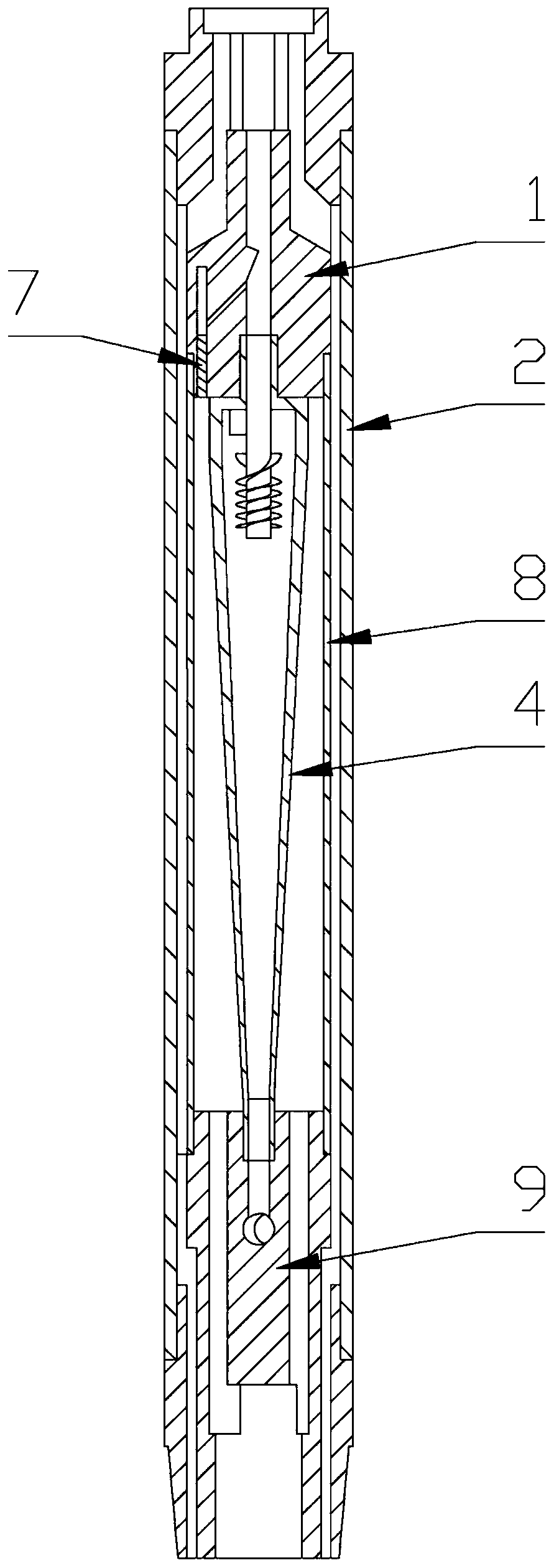
[0035] When the number of separator 4 to be installed is one, the parallel assembly is not installed, and the lower plug 7 is installed at the bottom of the hydrate channel on the top nipple 1 to isolate the annulus from the hydrate channel, and the outer pipe 2 and the bottom Assembly connection, connect the separator 4 and the bottom inner pipe 8 of the bottom assembly with the top nipple 1, and connect the outer pipe 2 with the top assembly.
[0036] After the hydrate raw slurry enters the annulus through the hydrate raw slurry channel of the bottom sub-section 9, it enters the separator 4 and is separated into hydrate and mud sand, and the hydrate enters the hydrate channel of the top sub-section 1 through the top outlet of the separator 4 In the upper row, the mud and sand enter the mud and sand channel of the bottom nipple 9 through the mud sand outlet at the bottom of the separator 4, and are finally discharged from the backfill pipe 6. At the same time, the seawater pas...
Embodiment 2
[0038] When the number of separators 4 to be installed is two or more, the total number of separators 4 required for installation is reduced by one parallel assembly, and the top of the separator 4 and the top of the outer pipe 2 of the first parallel assembly are connected to the top nipple 1 Connect and fix the position of the inner tube 3, connect the top of the separator 4 and the top of the outer tube 2 of each other parallel assembly with the previous parallel nipple 5, and fix the position of the inner tube 3, and install the lower plug 7 At the bottom of the hydrate channel of the parallel sub-joint 5 connected to the bottom assembly, the annulus of the bottom inner tube 8 is isolated from the hydrate channel, and the outer tube 2 is installed on the top sub-joint 1 through the parallel sub-joint 5. The separator 4 and bottom inner pipe 8 of the bottom assembly are connected with the last parallel sub-joint 5, while the outer pipe 2 is connected with the top assembly, a...
PUM
 Abstract
Description
Claims
Application Information
 - R&D
- Intellectual Property
- Life Sciences
- Materials
- Tech Scout
- Unparalleled Data Quality
- Higher Quality Content
- 60% Fewer Hallucinations
Browse by: Latest US Patents, China's latest patents, Technical Efficacy Thesaurus, Application Domain, Technology Topic, Popular Technical Reports.
© 2025 PatSnap. All rights reserved.Legal|Privacy policy|Modern Slavery Act Transparency Statement|Sitemap|About US| Contact US: help@patsnap.com


