Arrangement method for leaf apex timing sensor used for distinguishing blade multi-modal vibration

A sensor, multi-modal technology, used in vibration testing, engine testing, instrumentation, etc., can solve problems such as information loss, frequency aliasing of analysis results, and reconstructed signals are easily affected by noise, saving installation costs and space. , the effect of improving the accuracy

Active Publication Date: 2019-06-14
XI AN JIAOTONG UNIV
View PDF15 Cites 14 Cited by
  • Summary
  • Abstract
  • Description
  • Claims
  • Application Information

AI Technical Summary

Problems solved by technology

Since the data collected by the blade-tip timing sensor is seriously under-sampled, the traditional spectrum signal analysis method will cause the frequency aliasing of the analysis results, and the blade vibration parameters cannot be extra...

Method used


Image

  • Arrangement method for leaf apex timing sensor used for distinguishing blade multi-modal vibration
  • Arrangement method for leaf apex timing sensor used for distinguishing blade multi-modal vibration
  • Arrangement method for leaf apex timing sensor used for distinguishing blade multi-modal vibration

Examples


Embodiment Construction

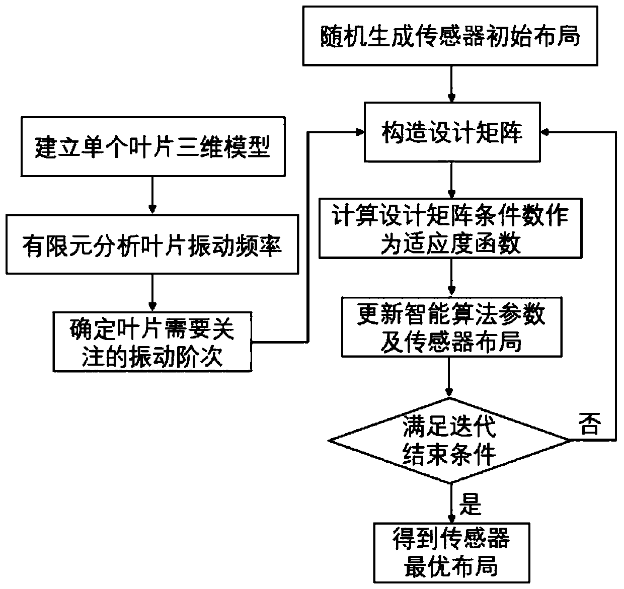
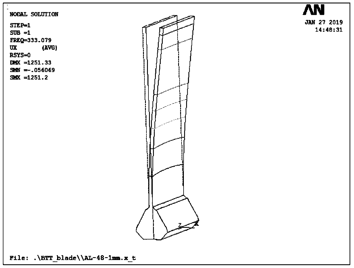
[0043] The following will refer to the attached figure 1 to attach Figure 6 Specific examples of the present invention are described in more detail. Although specific embodiments of the invention are shown in the drawings, it should be understood that the invention may be embodied in various forms and is not limited to the embodiments set forth herein. Rather, these embodiments are provided for more thorough understanding of the present invention and to fully convey the scope of the present invention to those skilled in the art.

[0044] It should be noted that certain terms are used in the specification and claims to refer to specific components. Those skilled in the art should understand that they may use different terms to refer to the same component. The specification and claims do not use differences in nouns as a way of distinguishing components, but use differences in functions of components as a criterion for distinguishing. "Includes" or "comprises" mentioned thr...


PUM


Abstract

The invention discloses an arrangement method for a leaf apex timing sensor used for distinguishing blade multi-modal vibration. The method comprises the following steps that: measuring the revolvingspeed and the vibration frequency of a blade, on the basis of the revolving speed and the vibration frequency of the blade, determining the vibration order of the blade and the number of the leaf apextiming sensors; on the basis of the installation angle of the leaf apex timing sensor and the vibration order, constructing the design matrix of a blade vibration model; calculating the condition number of the design matrix; and taking the condition number of the design matrix as a target function, and utilizing an optimization algorithm to enable the condition number of the design matrix a to achieve a minimum value so as to determine the installation angle of the leaf apex timing sensor.

Description

technical field [0001] The invention belongs to the technical field of vibration testing of aero-engine and gas turbine blades, in particular to a method for arranging blade-end timing sensors for identifying multi-mode vibration of blades. Background technique [0002] Rotating blades are important components in aero-engines. The harsh environment of the aero-engine is likely to cause the blades to vibrate, which in turn leads to damage such as cracks on the blades. Every year, airlines invest huge sums of money in engine maintenance and monitoring. In order to reduce the operation and maintenance cost of aero-engines while ensuring flight safety, condition-based maintenance is the goal pursued by airlines. When damage such as fatigue cracks occurs on the aeroengine blade, its vibration state will change. During the operation of the aero-engine, the real-time monitoring of the blade vibration parameters can effectively grasp the working condition and damage degree of the...

Claims


Application Information

Patent Timeline
IPC IPC(8): G01M15/12G01M15/00G01M7/02G06N3/00
Inventor 乔百杰许敬晖陈雪峰杨志勃翟智
Owner XI AN JIAOTONG UNIV
Why Eureka
Try Eureka