
Permanent magnet unit and radial distributed adjustable permanent magnetic safety coupler

A safety coupling, permanent magnet technology, applied in the direction of permanent magnet clutch/brake, etc., can solve the problems of limited transmission torque, complex structure, limited adjustability and so on

Pending Publication Date: 2019-06-14
嘉兴美盈德智能传动技术有限公司
View PDF0 Cites 5 Cited by
  • Summary
  • Abstract
  • Description
  • Claims
  • Application Information

AI Technical Summary

Problems solved by technology

This kind of transmission method has the following problems: as the transmission torque increases, the space occupied in the radial direction increases, and the transmission torque is limited. Especially in operation, the transmitted torque and speed are usually a fixed value, which cannot meet the use requirements.
Secondly, there are some couplings with radial transmission, but the existing radial transmission couplings on the market are complex in structure and limited in adjustability.

Method used


Image

  • Permanent magnet unit and radial distributed adjustable permanent magnetic safety coupler
  • Permanent magnet unit and radial distributed adjustable permanent magnetic safety coupler
  • Permanent magnet unit and radial distributed adjustable permanent magnetic safety coupler

Examples


Embodiment Construction

[0065] In order to more clearly describe the embodiments of the present invention or the technical solutions in the prior art, the specific embodiments of the present invention will be described below with reference to the accompanying drawings. Obviously, the drawings in the following description are only some embodiments of the present invention, and for those of ordinary skill in the art, other embodiments can also be obtained according to these drawings without creative efforts.

[0066] In order to keep the drawings concise, the drawings only schematically show the parts related to the present invention, and they do not represent its actual structure as a product. In addition, in order to make the drawings concise and easy to understand, in some drawings, only one of the components having the same structure or function is schematically shown, or only one of them is marked. As used herein, "one" not only means "only one", but also "more than one".

[0067] see Figure 1-...


PUM


Abstract

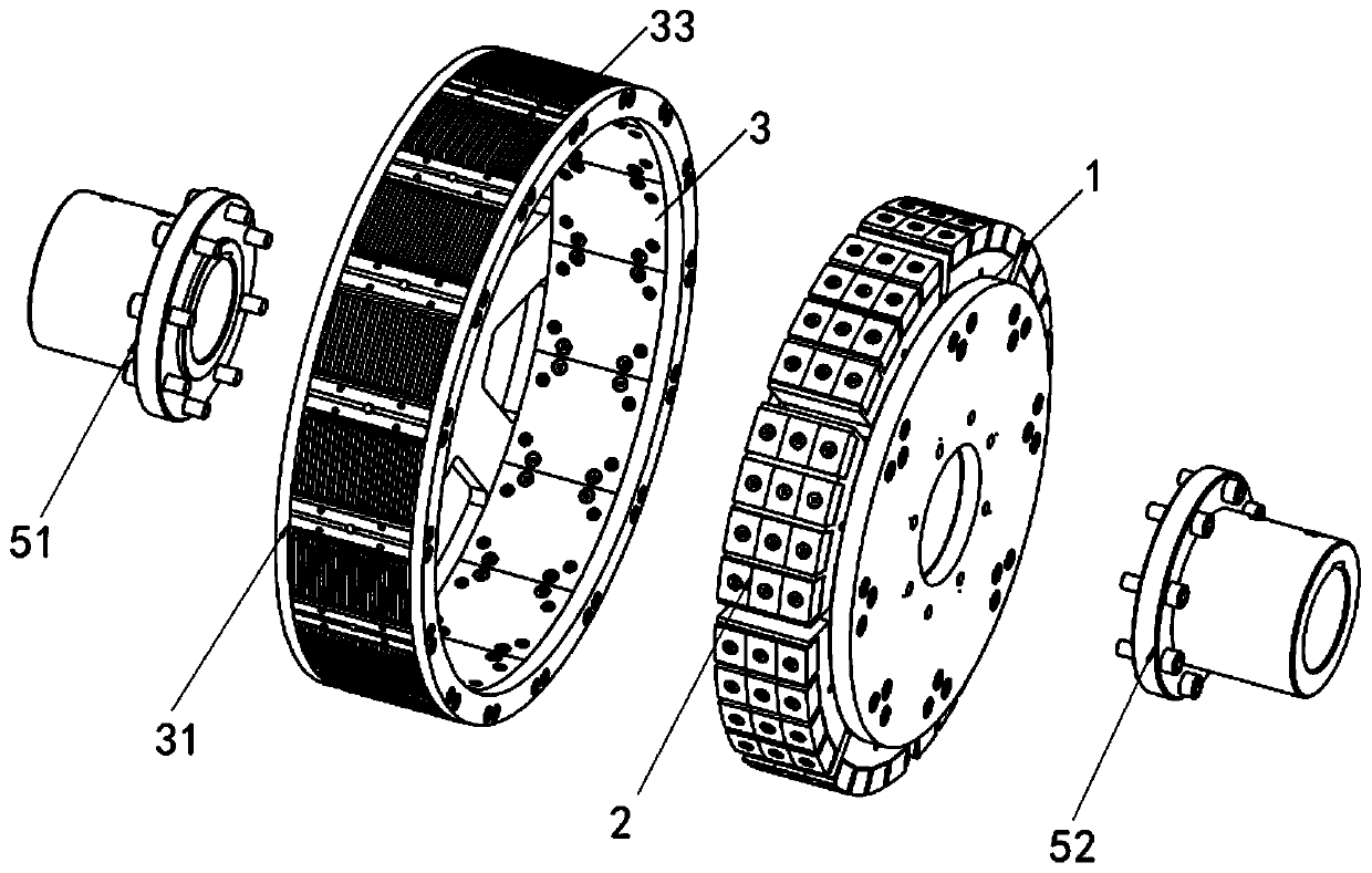
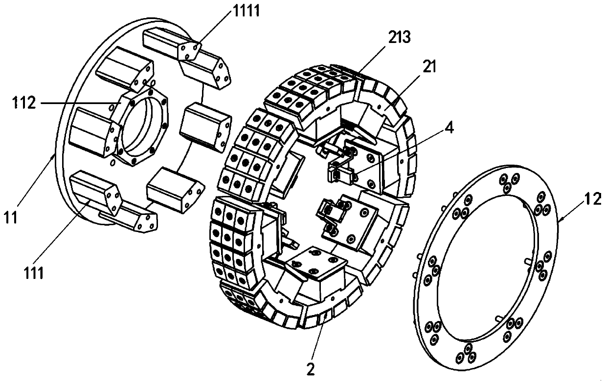
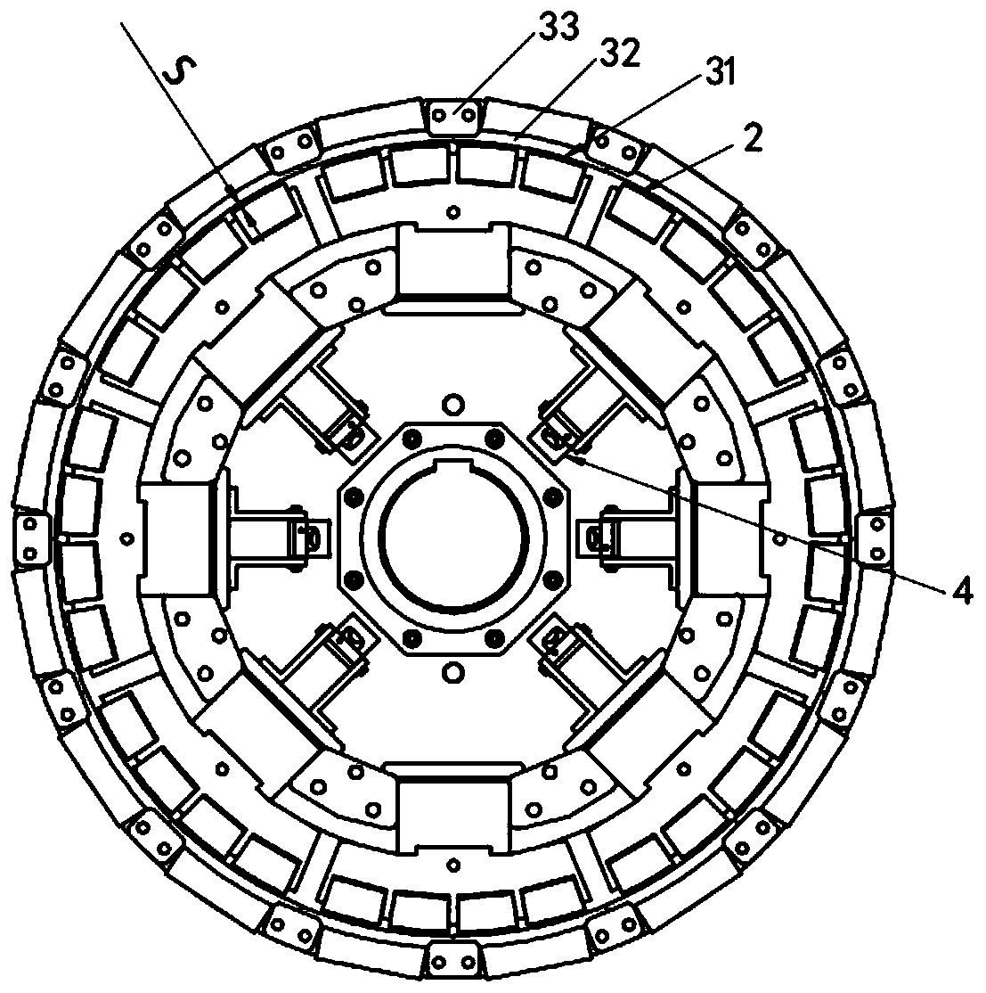
The invention relates to a radial distributed adjustable permanent magnetic safety coupler and a permanent magnet unit. A conductor assembly is arranged on the inner circumference of a coupler drivingdisc; a permanent magnet assembly is arranged on the outer circumference of a driven disc; the permanent magnet assembly consists of a plurality of permanent magnet units; a centrifugal mechanism isarranged on each permanent magnet unit; the conductor assembly and the permanent magnet assembly rotate relatively to generate a magnetic field, and the centrifugal mechanisms are switched between anopen state and a closed state so as to regulate a size of a gap between each permanent magnet unit and the conductor assembly; each permanent magnet unit comprises a limiting plate, a magnet fixing frame and a permanent magnetic block; and one side of each limiting plate is connected with the corresponding centrifugal mechanism and the other side of the limiting plate is connected with the corresponding magnet fixing frame. According to the invention, by arranging the permanent magnet units in a radial circumference distribution mode, a torsion is guaranteed to be regulated according to a rotating speed in the running process of the permanent magnetic safety coupler, uniformity of a moment is improved, a soft starting rate also can be regulated according to actual demands, transmission impact to a load end is effectively avoided, the application range is enlarged, and a protection effect is taken.

Description

technical field [0001] The invention relates to the technical field of couplings, in particular to a permanent magnet unit and a radially distributed adjustable permanent magnetic safety coupling. Background technique [0002] Coupling is a device that connects two shafts or shafts and rotating parts, and rotates together without disengaging in the process of transmitting motion and power (torque), and does not change the direction of rotation and the magnitude of torque during the transmission process. The permanent magnet coupling is a new type of coupling that connects the prime mover and the working machine through the magnetic force of the permanent magnet. It consists of two rotors that are not mechanically connected to each other. Connect the load shaft, the active rotor is equipped with conductor components, and the passive rotor is equipped with rare earth permanent magnets. The mutual movement between the rare earth permanent magnets and the conductors generates ed...

Claims


Application Information

Patent Timeline
IPC IPC(8): H02K49/10
CPCH02K49/10
Inventor 宋杭军
Owner 嘉兴美盈德智能传动技术有限公司
Learn More