Display device

A display device and display panel technology, which is applied in the directions of identification devices, optics, instruments, etc., can solve the problems of rebounding at the bend of the FPC and abnormal display of the display device.

Active Publication Date: 2019-06-14
XIAMEN TIANMA MICRO ELECTRONICS
View PDF6 Cites 1 Cited by
  • Summary
  • Abstract
  • Description
  • Claims
  • Application Information

AI Technical Summary

Problems solved by technology

[0004] However, due to the existence of the conductive cloth in the existing arrangement structure, the rebound force at the bend of

Method used


Image

  • Display device
  • Display device
  • Display device

Examples


Embodiment Construction

[0031] In order to better understand the technical solutions provided by the embodiments of the present application, a detailed description will be given below in conjunction with the accompanying drawings and specific implementation manners.

[0032] In order to facilitate the understanding of the technical solutions in this application, the prior art involved in this application is introduced below.

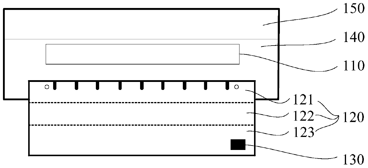
[0033] Please refer to figure 1 , figure 1 It is a schematic diagram of the display device in the prior art before the conductive cloth is provided. The display device includes a thin film transistor (Thin Film Transistor, TFT) substrate 140, a color filter (Color Filter, CF) substrate 150, a driver chip 110, a flexible printed circuit plate 120. The flexible printed circuit board 120 includes a bonding area 121 , a bending area 122 and a device area 123 .

[0034] Specifically, in order to discharge the static electricity of the display device, please continue to refer to ...


PUM


Abstract

The application provides a display device for reducing bounciness of a FPC (Flexible Printed Circuit). The display device comprises a display panel, a FPC board and a conduction part, wherein the display panel comprises a driving chip; the FPC board comprises a main body part and a projection part; the main body part comprises a binding region; the binding region comprises a plurality of golden fingers arranged along a first direction; the FPC board is electrically connected with the driving chip by the binding region; the projection part is arranged at at least one side edge of the main bodypart and comprises exposed copper; and the conduction part at least partially covers the driving chip and is grounded by the exposed copper.

Description

technical field [0001] The present application relates to the field of display technology, and in particular to a display device. Background technique [0002] An integrated driver chip (driver Integrated Circuit, driver IC) is disposed on a thin film transistor (Thin Film Transistor, TFT) glass substrate of the display device. During the use of the display device, a large amount of contact static electricity and air static electricity will be accumulated in the display device. If the static electricity is not released in time, the driver chip may be damaged. [0003] At present, in order to discharge the static electricity accumulated in the display device, the structure design of the existing display device is as follows: a conductive cloth is attached to the driver chip, and the conductive cloth is extended to the flexible printed circuit board (Flexible Printed Circuit, FPC) and then grounded, so that Discharge static electricity by grounding with a conductive cloth. ...

Claims


Application Information

Patent Timeline
IPC IPC(8): H05K1/02G09F9/00G02F1/1345
Inventor 黄阿海
Owner XIAMEN TIANMA MICRO ELECTRONICS
Why Eureka
Try Eureka