Refrigeration cycle device

A refrigeration cycle and refrigerant technology, applied in refrigerators, refrigeration components, refrigeration and liquefaction, etc., can solve the problem of inability to obtain noise reduction effects

Active Publication Date: 2022-05-17
DENSO CORP
View PDF6 Cites 0 Cited by
  • Summary
  • Abstract
  • Description
  • Claims
  • Application Information

AI Technical Summary

Problems solved by technology

In this regard, in the refrigeration cycle device described in Patent Document 1, only the high-pressure side refrigerant pressure is considered as a factor related to the refrigeration cycle, and therefore, as described above, an appropriate noise reduction effect cannot be obtained.

Method used


Image

  • Refrigeration cycle device
  • Refrigeration cycle device
  • Refrigeration cycle device

Examples


no. 1 approach

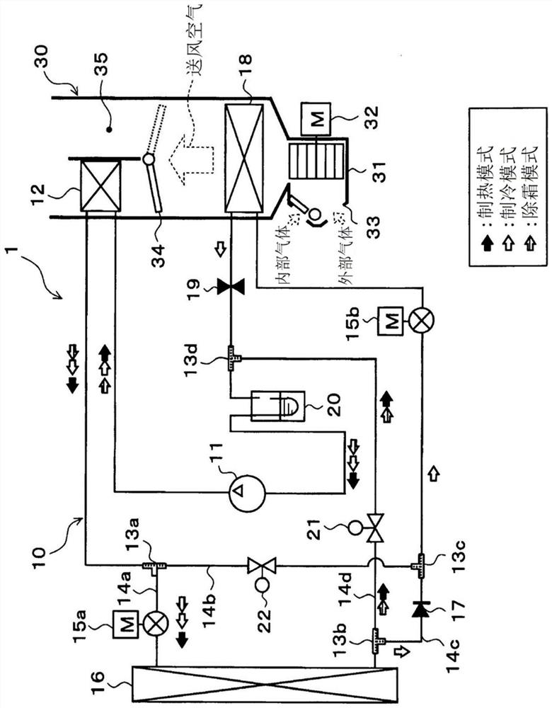
[0035] The refrigeration cycle device 10 of the first embodiment is applied to a vehicle air conditioner 1 mounted on an automobile. In the vehicle air conditioner 1 , the refrigeration cycle device 10 plays a role of cooling or heating the blown air blown into the vehicle interior which is a space to be air-conditioned. Therefore, the fluid to be heated in the first embodiment is blown air.

[0036] Further, the refrigeration cycle device 10 is configured to be switchable between a refrigerant circuit in a heating mode, a refrigerant circuit in a cooling mode, and a refrigerant circuit in a defrosting mode. Here, in the vehicle air conditioner 1 , the heating mode is an operation mode in which the blown air is heated and blown into the vehicle interior. In addition, the cooling mode is an operation mode in which the blown air is cooled and blown into the vehicle interior. Furthermore, the defrosting mode is an operation mode for defrosting frost formed on a heat exchanger (...

no. 2 approach

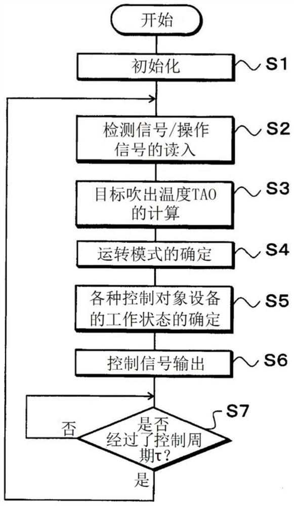
[0215] A second embodiment will be described with reference to the drawings. The vehicle air conditioner 1 of the second embodiment basically has the same configuration as that of the first embodiment except for the subroutine executed before determining the control signal to the compressor 11 in step S5 and the contents of the control map. Therefore, in the following description, the same reference numerals as those of the first embodiment denote the same configurations, and the previous descriptions are referred to.

[0216] In the second embodiment, the contents of the subroutine and the control map executed when determining the rotational speed upper limit value NcUL of the compressor 11 in step S5 are different from those of the first embodiment described above. Hereinafter, points of difference between the vehicle air conditioner of the second embodiment and the first embodiment will be described with reference to the drawings.

[0217] The refrigeration cycle apparatus...


PUM


Abstract

The refrigerating cycle device of the present invention includes: an electric compressor (11) that compresses and discharges a refrigerant; a heating heat exchanger (12, 16) that heats a fluid using the high-pressure refrigerant discharged from the electric compressor as a heat source; The decompression device (15a, 15b) that decompresses the refrigerant flowing out of the heat exchanger for heating; the evaporator (16, 18) that evaporates the refrigerant decompressed by the decompression device; the rotational speed of the electric compressor A rotational speed control unit (40a) that performs control. The high-pressure side refrigerant pressure (Pc) accompanying the refrigerant in the range from the discharge side of the electric compressor to the inlet side of the pressure reducing device relative to the range from the outlet side of the pressure reducing device to the suction port of the electric compressor As the pressure ratio (Pc / Ps) of the low-pressure side refrigerant pressure (Ps) of the refrigerant inside increases, the rotation speed control unit lowers the upper limit value (NcUL) of the rotation speed of the electric compressor.

Description

[0001] Cross-reference of related applications [0002] This application is based on Japanese Patent Application No. 2016-244155 filed on December 16, 2016, and the description thereof is incorporated herein. technical field [0003] The invention relates to a refrigeration cycle device. Background technique [0004] The refrigeration cycle apparatus described in Patent Document 1 is configured such that the upper limit value of the rotational speed of the compressor is lowered as the pressure of the high-pressure side refrigerant in the refrigeration cycle increases. Since the high-pressure side refrigerant pressure has a high correlation with compressor noise, this refrigeration cycle apparatus is intended to suppress compressor noise when the high-pressure side refrigerant pressure becomes high by controlling the compressor as described above. [0005] In addition, the refrigeration cycle apparatus described in Patent Document 1 is configured such that the upper limit va...

Claims


Application Information

Patent Timeline
Patent Type & Authority Patents(China)
IPC IPC(8): B60H1/22B60H1/32F25B1/00F25B47/02
CPCB60H1/22B60H1/32B60H1/00921B60H2001/00961B60H1/321B60H2001/325B60H2001/3272F25B5/04F25B2400/0409F25B2400/0411F25B2700/2104F25B2700/2106F25B2700/1931F25B2700/2117F25B49/02F25B41/20F25B41/24B60H1/00428F25B49/022
Inventor 多田和弘丸山健一野村富士夫
Owner DENSO CORP
Why Eureka
Try Eureka