Control device for working vehicle

A technology for control devices and engineering vehicles, which is applied in the direction of control devices, electrical controls, vehicle components, etc., and can solve the problems of large pump discharge, large heat energy loss, and large pressure oil overflow, so as to suppress overflow and reduce heat. The effect of energy loss

Active Publication Date: 2010-01-20
NIHON KENKI CO LTD
View PDF2 Cites 22 Cited by
  • Summary
  • Abstract
  • Description
  • Claims
  • Application Information

AI Technical Summary

Problems solved by technology

However, in this state, since the discharge volume of the pump is large, the overflow volume of the pressure oil passing through the relief valve increases, resulting in a large loss of heat energy.

Method used


Image

  • Control device for working vehicle
  • Control device for working vehicle
  • Control device for working vehicle

Examples


no. 1 approach

[0027] Below, refer to Figure 1 to Figure 8 A first embodiment of the control device for a construction vehicle according to the present invention will be described.

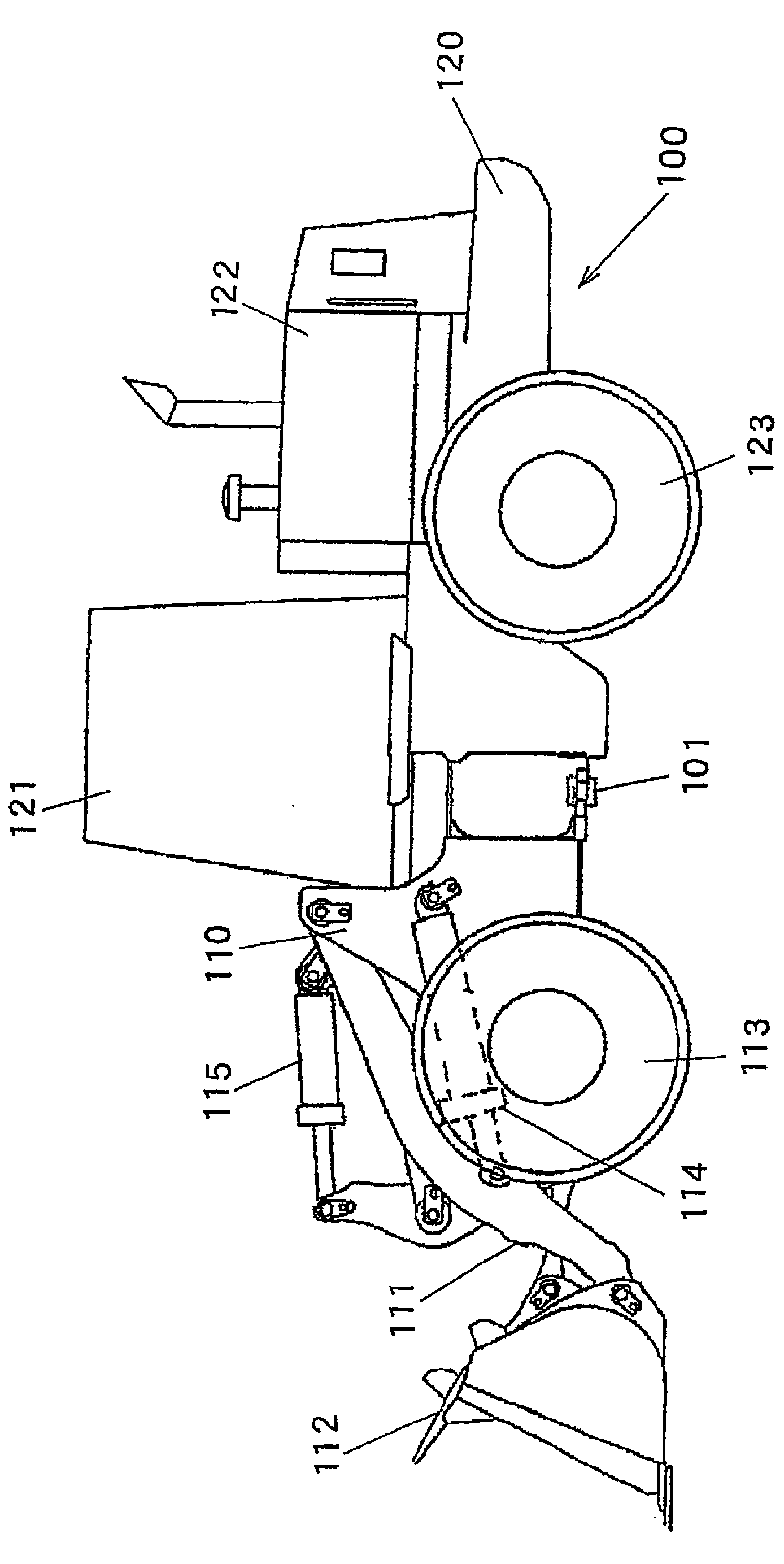
[0028] figure 1 It is a side view of a wheel loader which is an example of a construction vehicle to which the travel control device according to this embodiment is applied. The wheel loader 100 is composed of a front body 110 having an arm 111 , a bucket 112 , wheels 113 , and the like, and a rear body 120 having a cab 121 , an engine room 122 , wheels 123 , and the like. The arm 111 is driven by the arm hydraulic cylinder 114 to rotate in the vertical direction (pitch motion), and the bucket 112 is driven by the bucket hydraulic cylinder 115 to rotate in the vertical direction (unloading or shoveling). The front body 110 and the rear body 120 are rotatably connected to each other by a center pin 101 , and the front body 110 is bent left and right relative to the rear body 120 by expansion and contraction of...

no. 2 approach

[0057] refer to Figure 9 ~ Figure 11 A second embodiment of the control device for a construction vehicle according to the present invention will be described.

[0058] The second embodiment differs from the first embodiment in the processing in the speed upper limit value setting section of the controller 10 . That is, in the first embodiment, the upper limit value Nlim of the engine rotational speed is lowered to Ns on the condition that the travel circuit pressure Pt is equal to or greater than the predetermined value Pts and the working circuit pressure Pf is equal to or greater than the predetermined value Pfs. Here, the upper limit Nlim is lowered on the condition that the depression amount of the accelerator pedal 9 is equal to or greater than a predetermined value, the vehicle speed is equal to or less than a predetermined value, and the working circuit pressure Pf is equal to or greater than a predetermined value. Hereinafter, differences from the first embodiment w...


PUM


Abstract

A control device for a working vehicle, the device including a circuit (HC1) for traveling constructed as a closed circuit by interconnecting a variable displacement hydraulic pump (2) driven by an engine (1) and a variable displacement hydraulic motor (3), a circuit (HC2) for working having a hydraulic pump (4) for working driven by the engine (1) and also having hydraulic actuators (114, 115) for working driven by pressurized oil from the hydraulic pump (4), a relief valve (14) for relieving pressurized oil in the circuit (HC1) for traveling, rotational speed control sections (10, 18) for controlling the speed of the engine according to the amount of operation of an accelerator pedal (9), condition detection sections (21, 22) for detecting the vehicle being simultaneously in both a high load travel condition and a high load work condition, and a speed limit section (10) which, when the condition detection sections (21, 22) detect that the vehicle is simultaneously in both high load travel and high load work conditions, reduces an upper limit value (Nlim) of the engine speed.

Description

technical field [0001] The invention relates to a control device for engineering vehicles such as wheel loaders. Background technique [0002] Conventionally, there is known a device that controls the maximum value of the oil discharge volume of a hydraulic motor for travel in accordance with the discharge pressure of a hydraulic pump for work in a construction vehicle such as a wheel loader that has an HST travel circuit and a work circuit. limit to reduce driving force (for example, refer to Patent Document 1). In the device described in this Patent Document 1, the HST pump and the working hydraulic pump are driven by the engine, and the pump discharge amount changes according to the engine rotational speed. In addition, the driving pressure of the HST circuit is limited by the relief valve. [0003] Patent Document 1: Japanese Patent No. 2818474 [0004] However, during excavation, since the operator needs to shovel a large amount of earth and sand into the bucket, it ...

Claims


Application Information

Patent Timeline
Patent Type & Authority Applications(China)
IPC IPC(8): F02D29/00E02F9/22F02D29/04F02D45/00F02D29/02
CPCF15B2211/5059B60W2540/10F15B7/005F02D41/021E02F9/2232F16H61/4148F15B2211/6313E02F9/2253F15B2211/7058F02D31/009F15B2211/20553B60W30/184F15B2211/613F02D29/02B60W10/30F15B7/008F15B2211/20561F02D41/0205E02F9/2246F16H61/47B60W10/103E02F9/22F02D29/00F02D29/04F02D45/00
Inventor 兵藤幸次日高伸幸吉川正规竹山刚史长南和夫山崎恭央
Owner NIHON KENKI CO LTD
Why Eureka
Try Eureka