Medicine taking and liquid diet feeding device for severe intracardiac patients

A technology for patients and severe cases, applied in the medical field, it can solve the problems of mixing liquid medicine or food, sedimentation of liquid medicine or food, and inability to control accurately, and achieve the effect of comfortable use, easy consumption and good taste.

Inactive Publication Date: 2019-06-18
周开江
View PDF6 Cites 3 Cited by
  • Summary
  • Abstract
  • Description
  • Claims
  • Application Information

AI Technical Summary

Problems solved by technology

However, the outflow of the medicinal liquid cannot be accurately controlled, and it is only controlled by the knob, which is inconvenient to operate; in addition, the internal medicinal liquid or food cannot be stirred, resulting in precipitation of the medicinal liquid or food, which affects taking

Method used


Image

  • Medicine taking and liquid diet feeding device for severe intracardiac patients
  • Medicine taking and liquid diet feeding device for severe intracardiac patients
  • Medicine taking and liquid diet feeding device for severe intracardiac patients

Examples


Embodiment 1

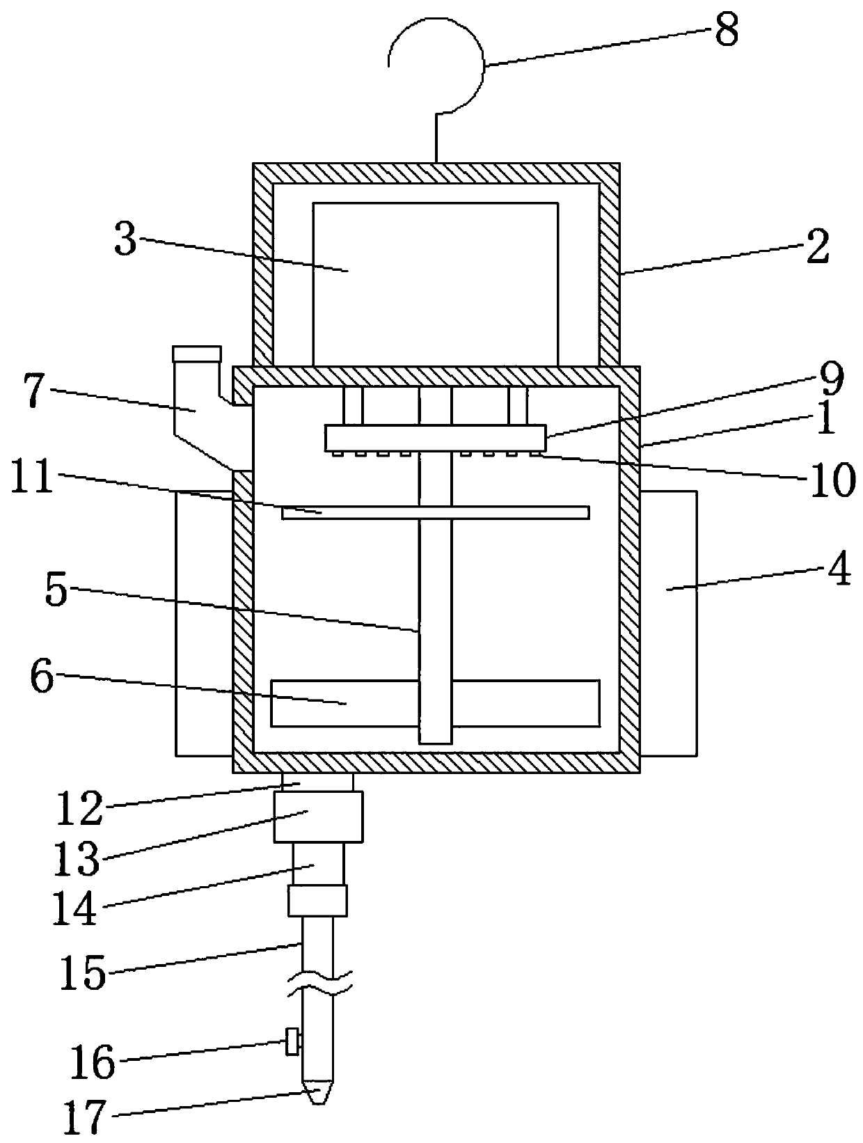
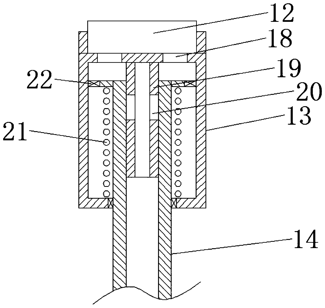
[0019] Please refer to the figure, in the embodiment of the present invention, a medicine-intake liquid food appliance for severe heart patients includes a housing 1, an outer cover 2, a feeding tube 7, a hook 8, a liquid outlet 12, an output tube 15, a valve 16 and Drinking spout 17; the outer cover 2 is fixed on the top of the housing 1, the hook 8 is located at the top of the outer cover 2, and is suspended by the hook 8, and the top of the side wall of the housing 1 is connected with a feed pipe 7 with an opening facing upward, and the feed pipe 7 A sealing cover is provided on the opening thread, and the liquid medicine or liquid food is fed into the housing 1 through the feed pipe 7; The cover 4 heats the inside of the housing 1 to make the temperature in the housing 1 suitable for drinking by the patient; a liquid outlet 12 is connected to the bottom of the housing 1 to discharge the liquid medicine or food in the housing 1 .

[0020] The lower end of the liquid outlet ...

Embodiment 2

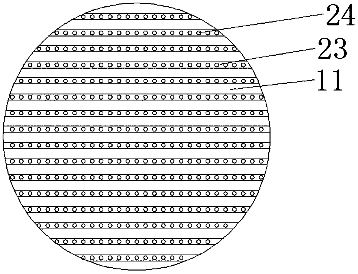
[0023] On the basis of Embodiment 1, a motor 3 is fixedly installed in the outer cover 2, the output shaft of the motor 3 extends vertically downward into the housing 1, and the output shaft of the motor 3 is fixedly connected with a vertical stirring shaft 5 , the upper and lower ends of the stirring shaft 5 are fixed with a plurality of horizontal stirring blades 6, the stirring shaft 5 drives the stirring blades 6 to rotate, and the liquid inside is stirred to avoid precipitation at the bottom; a horizontal cleaning plate 11 is also fixed on the stirring shaft 5 The upper surface of the cleaning tray 11 is provided with several horizontal diversion grooves 23, the diversion grooves 23 run through the cleaning tray 11, so that the liquid in the diversion grooves 23 flows out from both ends, and the bottom of the diversion grooves 23 is uniformly provided with Several diversion holes 24 allow a part of the liquid in the diversion groove 23 to fall from the diversion holes 24; ...


PUM


Abstract

The invention relates to the medical field and particularly discloses a medicine taking and liquid diet feeding device for severe intracardiac patients. The device comprises a casing, an outer cover,a feeding pipe, a hook, a liquid outlet, an output pipe, a valve and a drinking mouth, wherein the lower end of the liquid outlet is in threaded communication with a fixing pipe, a sealing pipe is coaxially fixed in the center of the fixing pipe, and the upper end of the sealing pipe is connected on a baffle in a sealed manner; the outer side of the sealing pipe is coaxially sleeved with a pullingpipe, a support check ring is fixed on the outer wall of the upper end of the pulling pipe, the outer side of the pulling pipe is sleeved with a support spring, and multiple communicating holes communicated with the inside are formed in the side wall of the middle of the sealing pipe. Downward flow of liquids can be well controlled by the pulling pipe capable of being pulled downwards, so that medicine liquids or liquid diet flow down slowly, flowing out of a large quantity of liquids after opening of the valve is avoided, eating is facilitated, patients can use the device more comfortably, and the device is simple to operate and convenient to use only by pulling the pulling pipe.

Description

technical field [0001] The invention relates to the medical field, in particular to a medicine-injecting liquid food appliance for severe cardiac patients. Background technique [0002] The utensils for hospitalized critically ill patients to take medicine or liquid food are usually porcelain bowls or cups. These utensils are not fully functional. Some critically ill patients are lying on the hospital bed and cannot get up to drink medicine or liquid food. The feeding operation is time-consuming and labor-intensive and very troublesome. [0003] A Chinese patent (notification number: CN 202236369 U, announcement date: 2012.05.30) discloses a liquid food feeding device for critically ill patients. Seriously ill patients take medicine liquid or other liquid liquid food, and the operation is simple and convenient, and heating is easy. However, the outflow of the medicinal liquid cannot be accurately controlled, and it is only controlled by the knob, which is inconvenient to o...

Claims


Application Information

Patent Timeline
Patent Type & Authority Applications(China)
IPC IPC(8): A61J15/00A61J7/00
Inventor 狄秀婷狄秀华
Owner 周开江
Why Eureka
Try Eureka