
Feeding method and automatic feeding mechanism of bending machine

An automatic feeding and bending machine technology, applied in the field of bending machines, can solve problems such as affecting the feeding process, increasing production costs, and low work efficiency, and achieving the effects of high production efficiency, fast feeding, and reduced production costs.

Pending Publication Date: 2019-06-18
OMS MASCH CO LTD
View PDF0 Cites 1 Cited by
  • Summary
  • Abstract
  • Description
  • Claims
  • Application Information

AI Technical Summary

Problems solved by technology

[0002] The bending machine is a commonly used equipment in mechanical manufacturing. The existing bending machine is very mature in technology, but there are still the following deficiencies in actual use: it is necessary to feed a single tube or bar into the bending machine during the production process. In the clamping device, most of the existing methods rely on workers to complete it. Manual feeding is labor-intensive, and the work efficiency is low, which will increase production costs; The axial direction of the material feeds the tube or bar into the clamping device. Using this feeding method is easy to affect the feeding process because the end face of the tube or bar is against the clamping device.

Method used


Image

  • Feeding method and automatic feeding mechanism of bending machine
  • Feeding method and automatic feeding mechanism of bending machine
  • Feeding method and automatic feeding mechanism of bending machine

Examples


Embodiment Construction

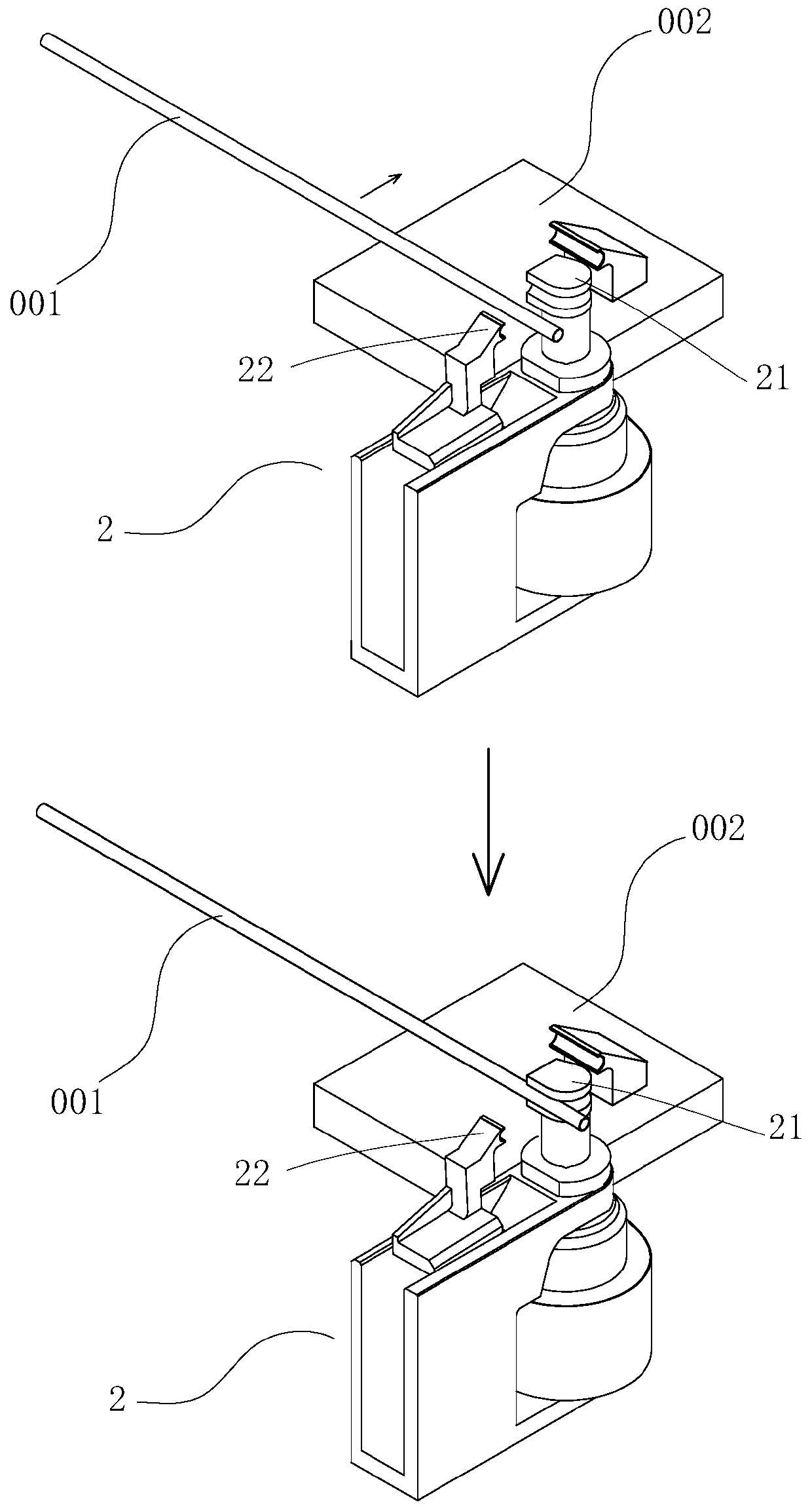
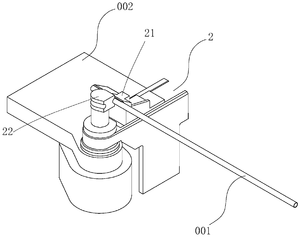
[0032] The specific embodiments of the present invention will be described in detail below with reference to the accompanying drawings.

[0033] The invention provides a method for feeding a bending machine, which comprises the following steps:

[0034] S1. The clamping device 2 of the bending machine is rotated 180° from the initial position to the receiving position;

[0035]S2. Translate and place the tube or bar 001 at the round die 21 of the clamping device 2, and then the clamping unit 22 of the clamping device 2 acts to clamp the tube or bar 001; preferably The specific operation process of translating and placing the tube or bar 001 at the circular die 21 of the clamping device 2 is as follows: first translate the tube or bar 001 along its axis direction, and then move the tube or bar 001 001 is placed at the circular die 21 along the direction perpendicular to its axis;

[0036] S3, the clamping device 2 is reversely rotated 180° from the receiving position to retur...


PUM


Abstract

The invention relates to a feeding method of a bending machine. The method includes the steps that a clamping device forwardly rotates by 180 degrees to reach a material receiving position from an initial position; pipes or bars are horizontally moved and put onto a circular mold and then a mold clamping unit moves and further clamps the pipes or the bars; the clamping device reversely rotates by180 degrees to return to the initial position from the material receiving position; the mold clamping unit moves and releases the pipes or the bars, and then the pipes or the bars are moved in the axis direction; and the mold clamping unit moves and further clamps the pipes or the bars and feeding is completed. The method has the beneficial effects of being rapid and accurate in feeding. The invention further provides an automatic feeding mechanism of the bending machine. A feeding device is adopted for accurate positioning and feeding, and then a first grabbing device is utilized to rapidly and accurately transfer the pipes or the bars onto the clamping device from the feeding device. The feeding method of the bending machine can be completed automatically, a traditional manual feeding mode is replaced, the beneficial effects of being high in production efficiency and suitable for mass production are achieved and meanwhile production cost is reduced.

Description

【Technical field】 [0001] The invention relates to the technical field of bending machines, in particular to a feeding method and an automatic feeding mechanism for a bending machine. 【Background technique】 [0002] The bending machine is a commonly used equipment in machinery manufacturing. The existing bending machine is technically mature, but in actual use, there are still the following shortcomings: in the production process, it is necessary to feed a single tube or bar into the bending machine. In the clamping device, most of the existing methods rely on workers to complete the work. The manual feeding is labor-intensive, and the work efficiency is low, which will increase the production cost; in addition, in the existing technology, the bending machine is usually loaded along the pipe or rod. The tube or bar is fed into the clamping device in the axial direction of the material. This feeding method is easy to affect the feeding process because the end face of the tube ...

Claims


Application Information

Patent Timeline
IPC IPC(8): B21D43/00
Inventor 龙晓明胡海峰龙川
Owner OMS MASCH CO LTD
Learn More