Flattening device for road pavement concrete

A concrete and smoothing technology, applied in the direction of roads, roads, road repair, etc., can solve the problems of decreased smoothing effect, poor bearing capacity, cement cracks, etc., to increase the smoothing effect, enhance the smoothing effect, and reduce work. The effect of efficiency

Inactive Publication Date: 2019-06-18
HUNAN JINGZHENG EQUIP MFG
View PDF0 Cites 0 Cited by
  • Summary
  • Abstract
  • Description
  • Claims
  • Application Information

AI Technical Summary

Problems solved by technology

[0002] Road bridges are generally composed of subgrades, road surfaces, bridges, tunnel engineering and traffic engineering facilities. When laying roads, it is necessary to lay concrete on the road surface first, and then use a vibrating ruler to smooth the newly laid concrete. After laying cement work, if the concrete is uneven, the cement laid on the surface will crack and the bearing capacity will not be good
[0003] However, there are still certain defects in the existing concrete during grinding. Although the existing grinding device can grind the concrete, but because the vibration pump directly acts on the center of the pressing plate, the midpoint of the pressing plate is vibrated for a long time. , will cause the two ends of the pressing plate to be lifted, so that the grinding effect of the two ends will decrease, and the center vibration will make the pressure of the pressing plate on the concrete pavement uneven, and the grinding effect will not be very good. If there is a bend, the grinding device Bulky and inconvenient for smoothing concrete at bends

Method used


Image

  • Flattening device for road pavement concrete
  • Flattening device for road pavement concrete
  • Flattening device for road pavement concrete

Examples


Embodiment Construction

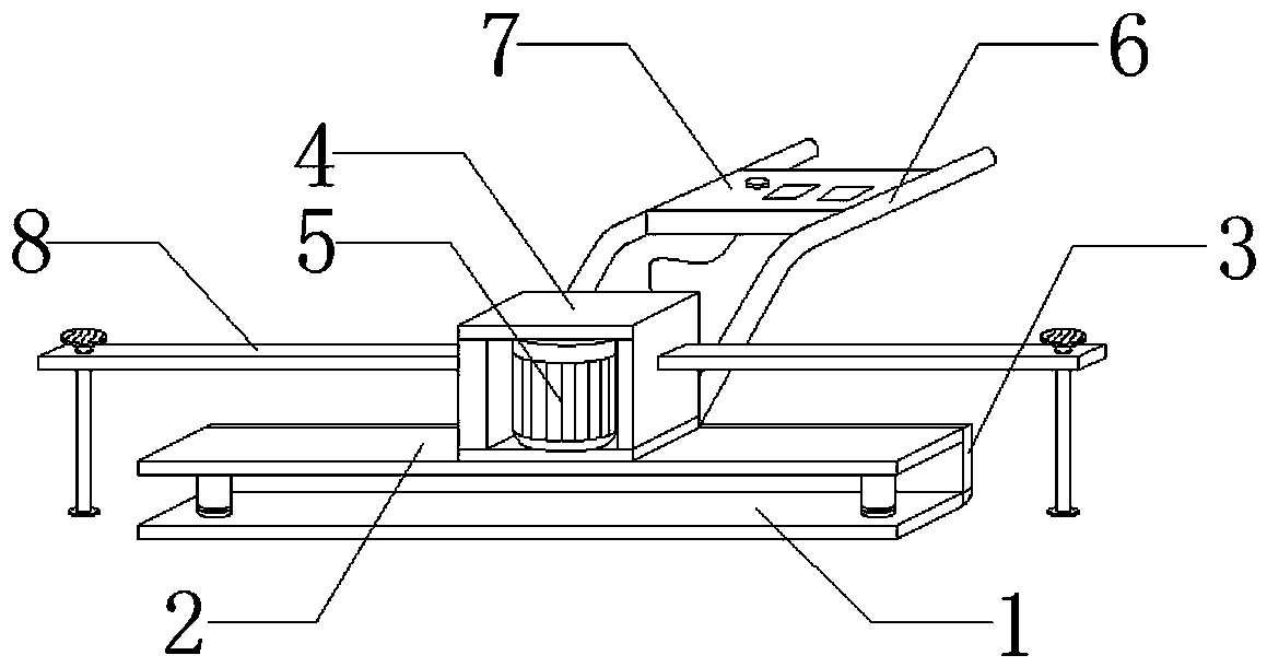
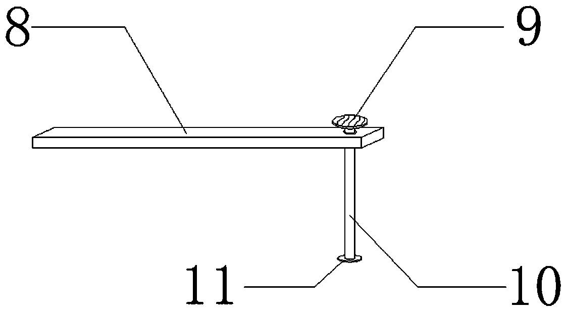
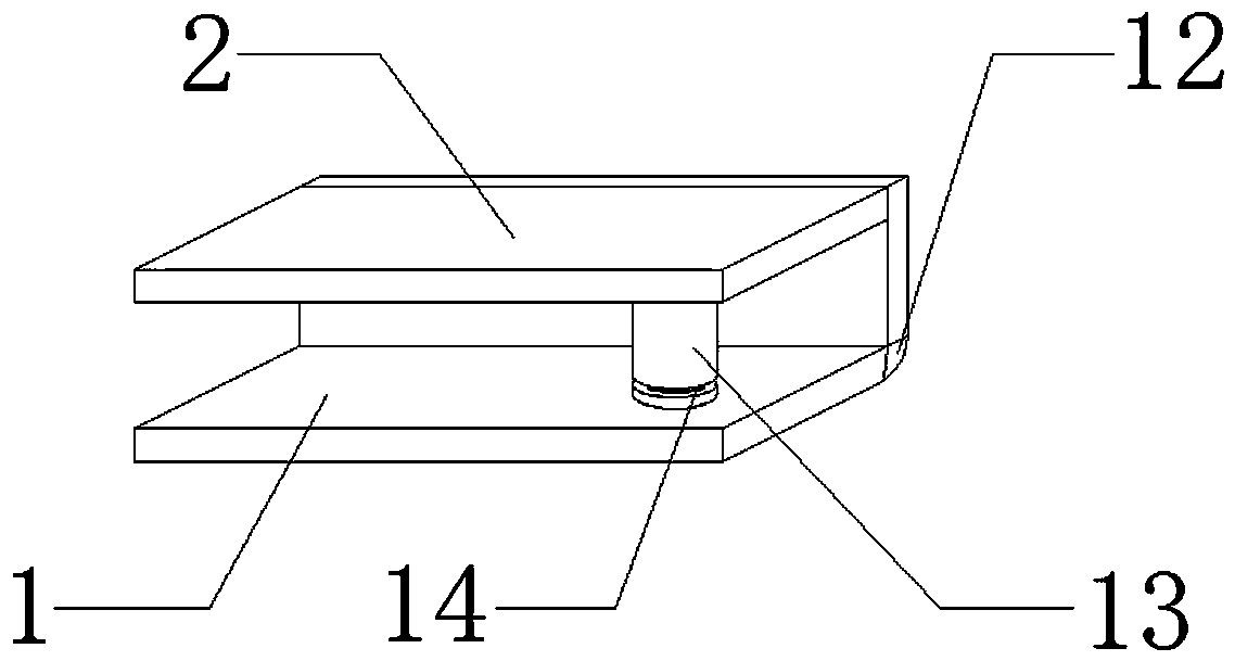
[0016] The technical solution of the present invention will be clearly and completely described below in conjunction with the accompanying drawings.

[0017] Such as Figure 1-3 As shown, the present invention comprises a pressing plate 1, a base plate 2 is installed above the pressing plate 1, a baffle plate 3 is arranged on one side of the pressing plate 1, a motor housing 4 is arranged on the top of the base plate 2, and a vibration pump 5 is installed inside the motor housing 4 , a handrail 6 is installed on one side of the motor housing 4, a control panel 7 is installed between the two handrails 6, a cross bar 8 is installed at both ends of the motor housing 4, and a foot pedal 9 is installed at one end of the cross bar 8, and the foot pedal The support bar 10 is installed below the plate 9, the bottom of the support bar 10 is provided with a backing plate 11, and one side of the pressing plate 1 is provided with a flat tip 12, and the bottom plate 2 is connected with the...


PUM


Abstract

The invention discloses a flattening device for road pavement concrete. The flattening device comprises a flattening plate, a bottom plate, a baffle, a motor shell, a vibration pump, a handrail, a control panel, a transverse rod, a pedal, supporting rods, a base plate, a pushing tip, transmission rods and a rubber pad. The transmission rod is respectively arranged at two ends of the flattening plate; the bottom plate is supported on the transmission rods, the vibration pump mounted on bottom plate; the vibration pump is not in direct contact with the flattening plate, instead, vibration is transmitted to the flattening plate through the two transmission rods; therefore, the pressure of the flattening plate on the road surface is uniform when the concrete road surface is flattened, the flattening effect can be improved, two ends of the flattening plate can be prevented from tilting after being used for a long time to influence the flattening of concrete, the working efficiency is improved, and the supporting rods are arranged at two ends of the motor shell and can rotate to flatten a curve part through the supporting rods. The flattening device has the characteristics that the flattening effect is enhanced, and the curve road surface can be flattened conveniently.

Description

technical field [0001] The invention relates to a smoothing device, in particular to a smoothing device for road laying concrete. Background technique [0002] Road bridges are generally composed of several parts such as roadbed, road surface, bridge, tunnel engineering and traffic engineering facilities. When laying roads, it is necessary to lay concrete on the road surface first, and then use a vibrating ruler to smooth the newly laid concrete. In the subsequent work of laying cement, if the concrete is uneven, cracks will appear on the cement laid on the surface, and the bearing capacity will not be good. [0003] However, there are still certain defects in the existing concrete during grinding. Although the existing grinding device can grind the concrete, but because the vibration pump directly acts on the center of the pressing plate, the midpoint of the pressing plate is vibrated for a long time. , will cause the two ends of the pressing plate to lift, so that the gri...

Claims


Application Information

Patent Timeline
IPC IPC(8): E01C19/40
Inventor 陈科军
Owner HUNAN JINGZHENG EQUIP MFG
Why Eureka
Try Eureka