A method of using an ultra-long anchor cable chute

A chute and anchor cable technology, applied in construction, infrastructure engineering, sheet pile wall, etc., can solve the problem that the anchor cable cannot be inserted into the anchor hole in a straight line, the pull-out resistance of the anchor cable fails to meet the design requirements, and the grouting of the anchor cable Insufficient section length and other problems, to achieve the effect of improving the success rate of decentralization, good economic benefits, and improving construction efficiency

Active Publication Date: 2020-11-13
CHINA CONSTR FIRST GRP THE SECOND CONSTR +1
View PDF6 Cites 0 Cited by
  • Summary
  • Abstract
  • Description
  • Claims
  • Application Information

AI Technical Summary

Problems solved by technology

[0005] The purpose of the present invention is to provide a method for using the ultra-long anchor cable chute, to solve the problem that the ultra-long anchor cable cannot be inserted into the anchor hole in a straight line when the existing non-casing construction is performed, and the two sides are repeatedly rubbed against each other. and the technical problem of the earthwork constantly collapsing and sliding due to the upper hole wall; it is also necessary to solve the serious hole wall collapse, the anchor hole diameter shrinkage and blockage, resulting in insufficient grouting of the anchor hole, insufficient length of the anchor cable grouting section, and the pullout force of the anchor cable. Technical issues that do not meet design requirements

Method used


Image

  • A method of using an ultra-long anchor cable chute
  • A method of using an ultra-long anchor cable chute
  • A method of using an ultra-long anchor cable chute

Examples


Embodiment 1

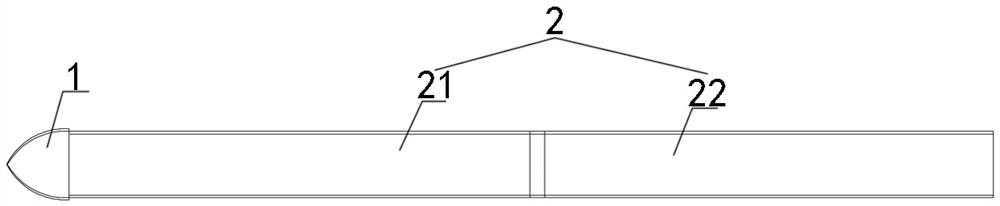
[0055] Embodiment one sees Figure 1-3 , 6, a super-long anchor cable chute, including a bar-shaped chute body, the chute body includes an end cap 1 and a chute section 2 connected sequentially from front to back, and the chute section It includes the first section 21 and at least one standard section 22.

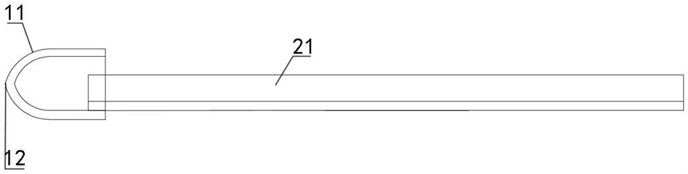
[0056] The end cap is a hollow cylinder, the end face of the front half of the end cap is a closed arc 11, the top of the arc is a tip 12, and the end face of the rear end of the end cap is open.

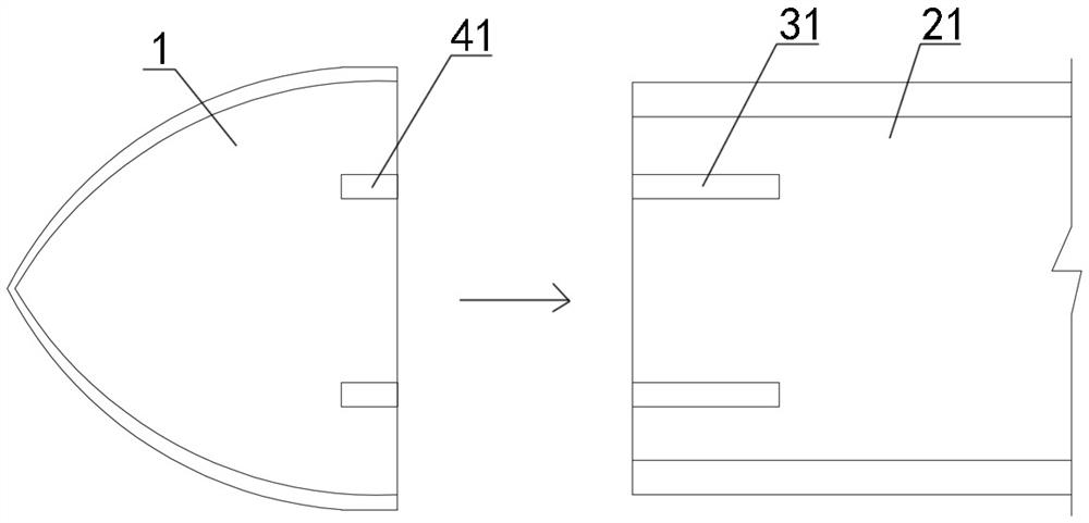
[0057] The front end of the first section 21 is connected to the rear end of the terminal cap 1 through a detachable connection structure. The detachable connection structure includes two grooves 31 arranged along the length direction on the lower side of the front end of the first section 21. It also includes that the position corresponding to the groove 31 on the inner wall of the second half of the end cap 1 has two ribs 4 matching the groove, and the lower side of the front ...

Embodiment 2

[0062] Embodiment two see figure 1 , 4 , 5, 7, and 9, the difference from Embodiment 1 is that the detachable connection structure includes that the front end groove bottom of the first section 21 has a clip parallel to the bottom of the groove and facing up and down, and the clip Including an upper clip 32 and a lower clip 42, the rear half of the upper clip 32 and the lower clip 42 are respectively fixedly connected with the upper and lower sides of the first groove bottom, the upper clip 32 and the lower clip 42 The front half of the head cap forms a receiving groove, and the rear end wall plate of the end cap is inserted into the receiving groove to abut against the end face of the front end of the first section.

[0063] The circular pipe is cut from a steel pipe, and the diameter of the pipe is slightly smaller than the diameter of the drilled hole. The connecting assembly includes a limit bolt 7 and a back plate 8 , and the lower side of the groove bottom at the head ...

Embodiment 3

[0066] Embodiment three see Figure 10-11 As shown, the difference from the second embodiment is that the chute section is formed by customized bending of thin steel plates, and the shape can be customized according to the needs, not completely circular arc shape, and the two upper ends of the segments form inwards. 14.

[0067] The connecting assembly includes a flange plate, flange bolts 6 and a protection plate, the rear chute section 2a is aligned with the connection end face of the previous chute section 2b, the flange plate is as wide as the chute section, and The bottom of the trough section is vertical, including a front flange plate 16 and a rear flange plate 17, the front flange plate 16 is fixedly connected to the tail end of the previous chute section 2b, and the rear flange plate 17 is fixedly connected to the rear chute At the head end of section 2a, flange bolt holes are respectively opened on the front flange plate 16 and the rear flange plate 17, and the flan...


PUM


Abstract

The invention discloses a super-long anchor cable sliding groove and a use method thereof. The super-long anchor cable sliding groove comprises an end cap and sliding groove sections, wherein the endcap and the sliding groove sections are successively connected from front to back, the sliding groove sections comprise a first section and one or more standard sections, the front end of the first section and the rear end of the end cap are connected through a detachable connecting structure, the sliding groove sections are connected end to end to be lengthened, and the head end of the rear sliding groove section and the tail end of the preceding sliding groove section are detachably connected through a connecting assembly. The super-long anchor cable sliding groove is especially for super-long anchor cables, a lengthening mode which is easy in operation, quick in lengthening, convenient to stack, and capable of being recycled advantageously is adopted by connection between parts of the sliding groove, the designed anchorage length and required pulling resistance of a super-long anchor cable are guaranteed, the anchor cable construction quality is guaranteed, the super-long anchor cable sliding groove can be recycled and reused, energy conservation and environment protection are achieved, and the good economic benefits are achieved.

Description

technical field [0001] The invention belongs to building slope support engineering, in particular to a non-casing ultra-long anchor cable lowering chute. Background technique [0002] For building slope support, anti-slide piles or lattice beams with anchor cables are generally used. Among them, in non-casing construction, when the anchor cable of the building slope is lowered, the steel strand of the anchor cable is generally lifted manually and inserted directly into the anchor hole. Many questions: [0003] 1. Due to the softness of the steel strands of the anchor cables, it is difficult to ensure that they are inserted into the anchor holes in a straight line during the manual lowering process. The friction and collisions on both sides and the upper hole walls will cause the earthwork on the hole walls to continuously collapse and slide. The deeper the anchor hole, the more difficult it is to lower the anchor cable. When the hole wall collapses seriously, the anchor ca...

Claims


Application Information

Patent Timeline
Patent Type & Authority Patents(China)
IPC IPC(8): E02D5/74E02D13/04
Inventor 王文涛师恩来刘卫东季文君于雁南牛小犇邹然杨晓丽
Owner CHINA CONSTR FIRST GRP THE SECOND CONSTR
Why Eureka
Try Eureka