Deep foundation pit supporting system and construction method thereof

A technology of support system and deep foundation pit, applied in the field of rail transit, can solve the problems of economic loss, installation deviation, increased difficulty in hoisting, etc., and achieve the effects of avoiding collapse and deformation, reducing operation time and high equipment utilization.

Inactive Publication Date: 2019-06-18
宁波用躬科技有限公司
View PDF3 Cites 4 Cited by
  • Summary
  • Abstract
  • Description
  • Claims
  • Application Information

AI Technical Summary

Problems solved by technology

[0003] The conventional foundation pit construction is excavated step by step. After the excavation of each layer of soil is completed, the support frame is lifted by large lifting equipment, and then it is hoisted to the design position for installation. The axial force is pre-added, but the above-mentioned construction method has the following disadvantages: 1. The installation of the support frame is visually positioned by the construction personnel, which often causes deviations in the installation, and often requires multiple adjustments to reach the design position. Time-consuming, between the excavation of each layer of soil and the completion of the installation of the support frame, the foundation pit has an unsupported exposure time of 8-12 hours, and there are certain safety hazards; 2. With the continuous increase of the excavation depth of the foundation pit , the difficulty of hoisting will also increase significantly, and there will often be problems of limited number of large-scale equipment and difficult turnover. In addition, the periodic utilization rate of equipment is low, which will cause unnecessary economic losses; 3. Affected by temperature difference and stress relaxation, there will be The loss of supporting axial force, with the loss of supporting axial force, the deformation of the foundation pit increases, which will have a negative impact on the deformation control of the foundation pit and the overall safety of the foundation pit

Method used


Image

  • Deep foundation pit supporting system and construction method thereof
  • Deep foundation pit supporting system and construction method thereof
  • Deep foundation pit supporting system and construction method thereof

Examples


Embodiment 1

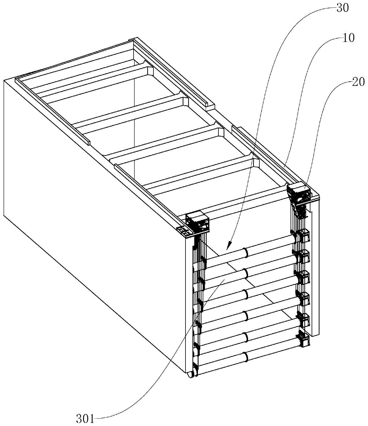
[0042] Embodiment 1: As shown in the figure, a deep foundation pit support system includes a crown beam 10 fixedly arranged on the top of the two walls of the foundation pit, and also includes two lifting brackets 20 and multiple sets of supporting devices 30, two lifting brackets 20 The brackets 20 are respectively fixed on the two crown beams 10, and each set of supporting devices 30 includes a support beam 301 and two lowering mechanisms 302, the supporting beam 301 is arranged horizontally between the two walls of the foundation pit, and the two lowering mechanisms 302 are respectively It is fixed on two lifting brackets 20 and is used to control the lifting of the support beam 301 in the foundation pit.

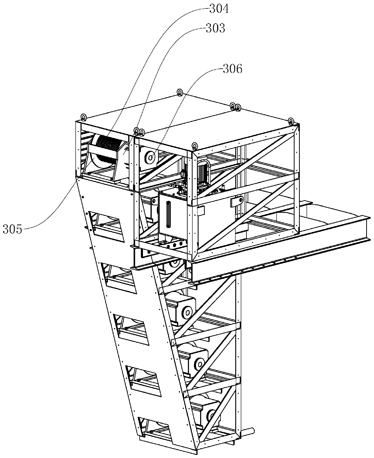
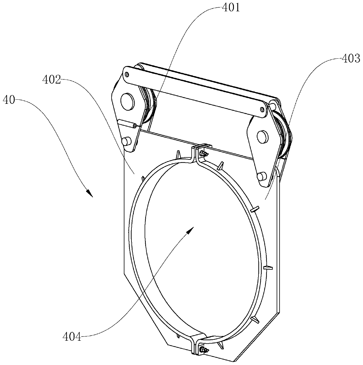
[0043] In this specific embodiment, each lowering mechanism 302 includes a winch support 303, a suspension cable 304, a reel 305, a hydraulic motor 306 for driving the reel 305 to rotate, and each end of the support beam 301 is equipped with a pre-installed hoop 40 , the...

Embodiment 2

[0048] Embodiment 2: As shown in the figure, a deep foundation pit support system includes a crown beam 10 fixedly arranged on the top of the two walls of the foundation pit, and also includes two lifting brackets 20 and multiple sets of supporting devices 30, two lifting brackets 20 The brackets 20 are respectively fixed on the two crown beams 10, and each set of supporting devices 30 includes a support beam 301 and two lowering mechanisms 302, the supporting beam 301 is arranged horizontally between the two walls of the foundation pit, and the two lowering mechanisms 302 are respectively It is fixed on two lifting brackets 20 and is used to control the lifting of the support beam 301 in the foundation pit.

[0049] In this specific embodiment, each lowering mechanism 302 includes a winch support 303, a suspension cable 304, a reel 305, a hydraulic motor 306 for driving the reel 305 to rotate, and each end of the support beam 301 is equipped with a pre-installed hoop 40 , the...

Embodiment 4

[0070] Embodiment 4: A method for foundation pit construction using a deep foundation pit support system, comprising the following steps:

[0071] S1: According to the design requirements, determine the total depth H of the excavated foundation pit, the total number n of support beams to be placed, the excavation depth of each layer of soil, and the support point of each layer of soil;

[0072] S2: Install crown beams on the top of the two walls of the foundation pit, and pour concrete support between the two crown beams. After pouring, install a lifting bracket and a lowering mechanism on each crown beam. After the installation is in place, carry out soil excavation;

[0073] S3: After the predetermined excavation depth of the first layer of soil is dug, stop excavation;

[0074] S4: hoisting the support beam into the excavated soil layer with a crane;

[0075] S5: Start the hydraulic motor, lower the suspension cable from the reel, make the suspension cable pass through th...


PUM


Abstract

The invention discloses a deep foundation pit supporting system and a construction method thereof. The deep foundation pit supporting system comprises top beams fixedly arranged at the tops of the twowall faces of a foundation pit, and further comprises two hoisting brackets and a plurality of sets of supporting devices, the two hoisting brackets are fixed to the two top beams correspondingly, and each set of supporting device comprises a supporting beam and two lowering mechanisms, wherein the supporting beam is transversely arranged between the two wall faces of the foundation pit, and thetwo lowering mechanisms are fixed to the two hoisting brackets correspondingly, and used for controlling rising and lowering of the supporting beam in the foundation pit. The deep foundation pit supporting system has the advantages that mounting is convenient and fast, the operation time is shortened, the equipment utilization rate is high, and supporting is firm.

Description

technical field [0001] The invention relates to the technical field of rail transit, in particular to a deep foundation pit support system and a construction method. Background technique [0002] With the rapid development of rail transit, there are more and more deep foundation pit projects in cities, and they are getting deeper and deeper. Generally, in order to ensure the safety of the underground structure construction and the surrounding environment of the foundation pit, the side walls of the foundation pit and the surrounding environment will be supported to prevent excessive deformation of the foundation pit or surface settlement. Separated from the rest, work is concentrated in areas enclosed by concrete walls. [0003] The conventional foundation pit construction is excavated step by step. After the excavation of each layer of soil is completed, the support frame is lifted by large lifting equipment, and then it is hoisted to the design position for installation. ...

Claims


Application Information

Patent Timeline
Patent Type & Authority Applications(China)
IPC IPC(8): E02D17/04E02D15/08
Inventor 朱宏伟董子博朱寰
Owner 宁波用躬科技有限公司
Why Eureka
Try Eureka